SatLink VSAT User Guide
Publication no. 101557
Copyright © 2009 – STM Group, Inc.
Page 11 (160)
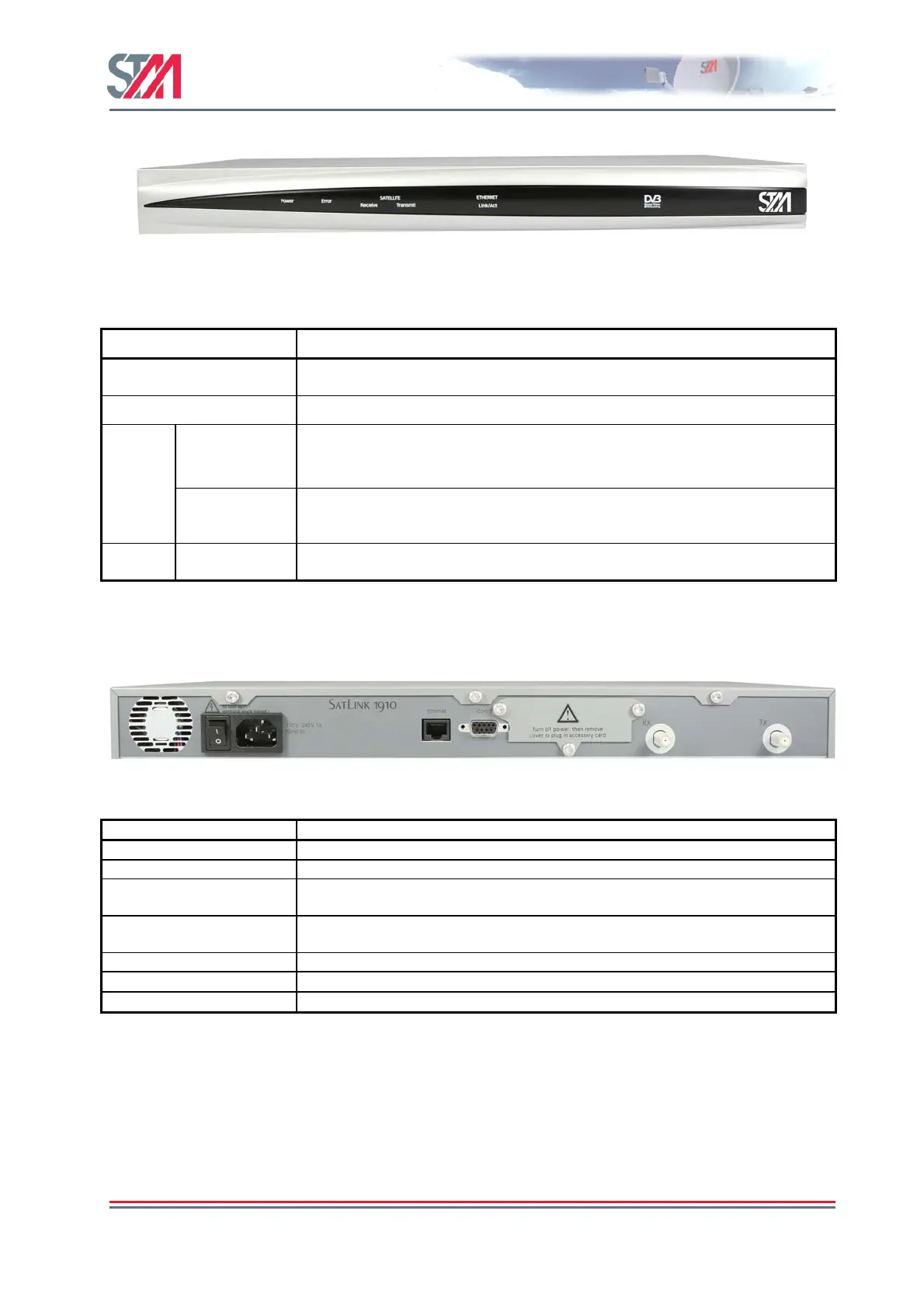
Figure 7: SatLink 1910 Front Panel
LED Colour, indicates
Power
Blue, lights steadily when power switch is on and unit is powered. Flashes when
loading software.
Error Red, lights steadily when an error event occurs and during reboot.
Satellite Receive Blue, flashes when the receiver is searching for the carrier.
Lights steadily when receiver is on and functioning properly.
Flashes when IP packets are received from the Satellite Interface (the Hub).
Transmit
Blue, flashes rapidly when a continuous wave (CW) is transmitted.
Lights steadily when the VSAT is logged on to the DVB-RCS Hub.
Flashes when IP packets are transmitted to the Satellite Interface (the Hub).
Ethernet Link/Act
Blue, lights steadily when Ethernet connectivity is OK.
Flashes slowly when Ethernet packets are transferred via the Ethernet interface.
Table 1: SatLink 1910 Front Panel LEDs
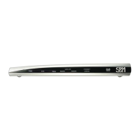
Figure 8: SatLink 1910 Rear Panel
Item Description
On/Off switch Power on (1) or off (0).
Power Connector Standard recessed plug for Power cord.
Ethernet
Connector
RJ45 connector for IP traffic to connect to a PC, Ethernet switch, IP router etc.
10BASE-T or 100BASE-T mode is detected automatically.
COM1
Connector
Nine pin connector for connecting CLI interface to a computer’s DB-9 serial
interface.
Cover for Accessory Card Not used.
RX coaxial jack
Coaxial 75 Ω F-type jack for the cable to the LNB.
TX coaxial jack
Coaxial 75 Ω F-type jack for the cable to the BUC.
Table 2: Description of SatLink 1910 Rear Panel