SatLink VSAT User Guide
Publication no. 101557
Copyright © 2009 – STM Group, Inc.
Page 131 (160)
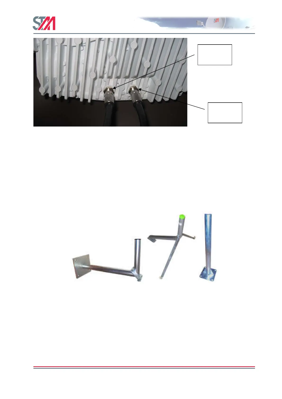
Figure 49: Connecting cables from IDU
The IF connectors are placed in the chassis of the SatLink 403x. A protrusion on the case indicates ‘RX’
and ‘TX’ so that they are easily distinguishable. Cable connectors should be tightened firmly, but use of
excessive force may damage the F-connectors on the transceiver.
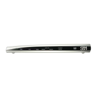
F.2 Assembly and installation of the antenna
Different mounting structures for antennas are shown below. From the left-hand side, we have an L-
shaped wall-mount, a three-leg mount and a standard straight mount. The tube diameter is 76 mm. For a
correct mounting the surface must be vertical or horizontal, respectively.
Non-penetrating roof-mounting structures (requiring no screws or bolts) may also be used if the customer
does not want to penetrate the roof. The foot can be rectangular, “H-shaped” or have another suitable
form. It must be loaded with at least 75 kg depending on the antenna size and maximum wind force.
Install the antenna and adjust pointing and polarization as described in the antenna manufacturer’s
installation instruction. After connecting the cables from the IDU to the transceiver (or BUC/LNB/OMT)
and completing the installation of the antenna with feed horn and transceiver (or BUC/LNB/OMT)
proceed with fine adjustment of antenna pointing and polarization assisted by the IDU as described in
section 9.3.
RX
connector
TX
connector