5
PART 1 • English
English
3.0 YOUR RECEIVER
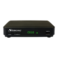
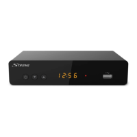
3.1 Front Panel
Fig. 2
USB Connects to USB storage device
3.2 Rear Panel
Fig. 3
1. ANT IN To connect an antenna for reception of broadcasting signal.
Active antennas can be supported with max. 5 V/500 mA DC.
2. TO TV To connect a TV set or to connect an extra receiver.
3. TV SCART Connector
To connect your receiver with your TV set using a SCART cable.
4. DVD/VCR SCART To connect to a Video or DVD recorder
5. S/PDIF Coaxial To connect your receiver to digital audio amplifier.
6. Power Cord Your receiver requires a voltage of 220-240V AC (Auto-selectable),
50/60Hz ±5%. Make sure to check the power specification before
connecting your receiver to the wall outlet.
3.3 Remote Control
Fig. 4
1. q Turns the receiver On/Standby
2. ! Mutes audio output of the receiver
3. PG+/PG- Page up/down (10 channels steps in channel list mode)
4. DTV/VCR To switch between TV and VCR mode
5. INFO Shows the actual channel information
6. VOL+/VOL- Volume up/down
7. MENU Opens the main menu/In menu you will get one step back
8. EXIT Exits from the menu or sub-menu
9. pq Menu Off: Change channel to previous/next.
Menu On: Moves the cursor up/down.
10. tu Menu Off: Increases/decreases the volume level.
Menu On: Change settings for specific Menus
11. OK Menu Off: Displays the current channel list
Menu On: Activates the highlighted menu item.
12. RECORD Records the TV program to the connected storage device
13. TIMESHIFT Activates the Timeshift function
14. 0~9 Channel selection or value input
15. EPG Shows the EPG (Electronic Program Guide) in TV mode
16. RECALL Back to previous shown channel
17. AUDIO Sets the current audio channel to left, right or stereo
18. TV/RADIO Toggles between TV or RADIO mode
19. FAV Favourite group selection
20. FILE Shows the record list (preconditioned file/s already recorded)
21. TTX Shows Teletext on OSD (On Screen Display)