Compact SCore Technical Info STUDER Professional Audio GmbH
4/22 13.Feb.06
1 Introduction
1.1 Definitions and Acronyms
Board: A complete PCB with all components mounted
Card: A board with its mechanical parts, ready for insertion in a system
MIMD: Multiple Instructions Multiple Data
VDCA: Virtual Dual Card Architecture
DSP: Digital Signal Processor
SH4: Hitachi RISC engine 7751R
PE: Processing Element (like DSP or SH4)
2 System Overview
2.1 Basics
The Compact SCore digital audio processing and IO unit consists of the following main blocks:
- The Host Card (Main System Controller running WinCE.net) on the AUX and I2C Bus
- Up to 6 Compact SCore DSP Cards (Hybrid) on the TDM, AUX and I2C Bus
- One Audio Clock Card serving as global audio clock source on the TDM Bus
- An optional Time Sync Card for synchronizing the System Clock
- A fully integrated D21m subset with 2 extra slots for GPIO Cards
Only the core relevant part is discussed in this document. For a reference to the D21m subsystem please consult
the D21m documentation.
2.2 Compact SCore System Architecture
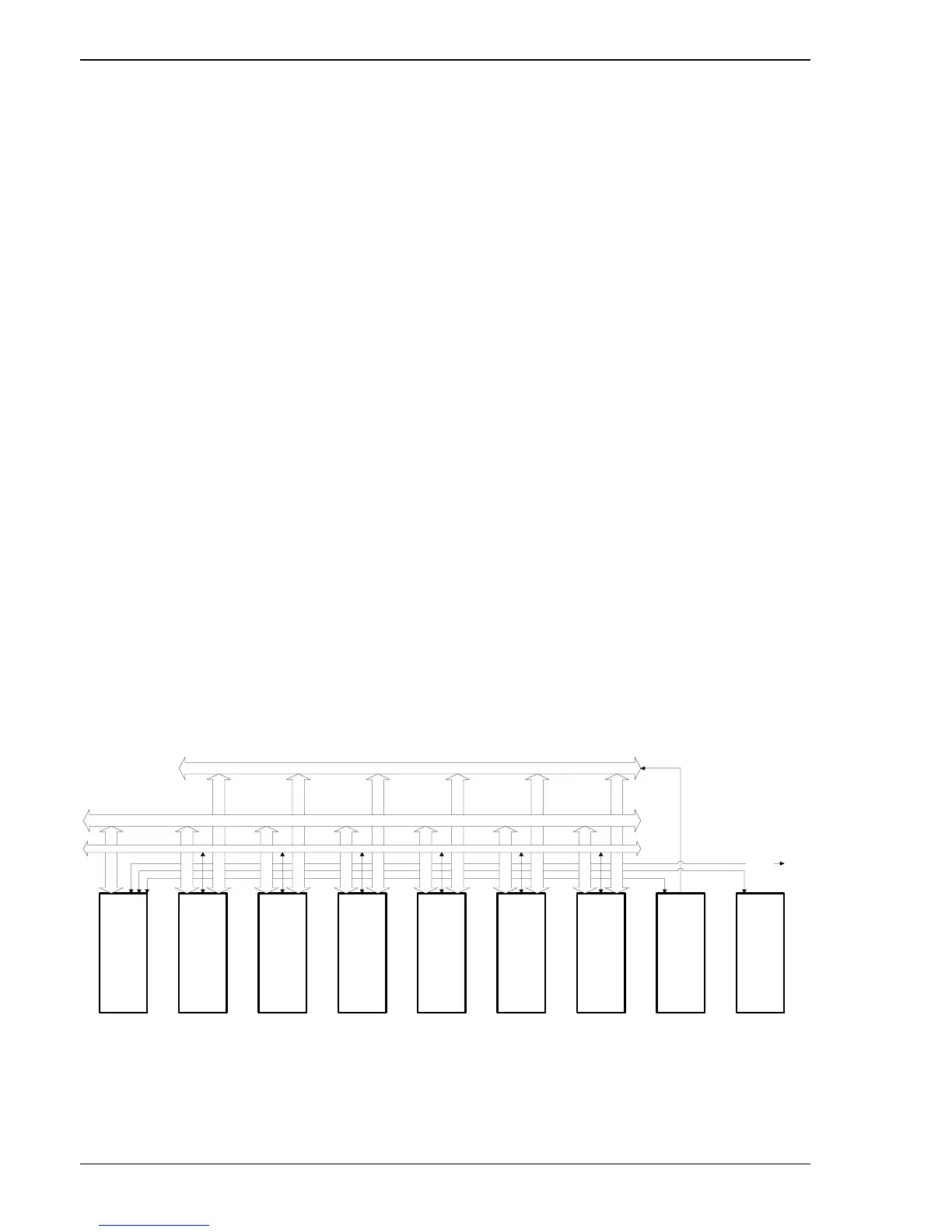
The following diagram gives a rough overview of the Compact SCore System Architecture. The AUX Bus is
implemented as a customized compact PCI implementation. All DSP Cards are booted and controlled via this
PCI Bus. Three point-to-point UART connections are used to control the Audio Clock (Com1), Time Sync
(Com2) and first HD (Com3) Card in the same Frame. The fourth UART (Com4) is available as either RS232 or
RS422 on the front panel of the Host Card. System monitoring is achieved using the I2C Bus.
TDM Bus
Host Card / Slot 0
DSP Card / Slot 1
DSP Card / Slot 2
DSP Card / Slot 3
DSP Card / Slot 4
DSP Card / Slot 5
DSP Card / Slot 6
AudioClock Card
TimeSync Card
AUX Bus
I2C Bus
HD Card
The high-speed inter-cluster communication fabric is based on our custom TDM Backplane using Virtual Dual
Card Architecture.

 Loading...


