SCore Live
24 SCore Live
Date printed: 28.02.11
For power supply to the fans and fan status monitoring, two connectors are
provided – one at the front, the second at the rear of the unit. They are con-
nected in parallel, so either one can be used depending on the application. If
any of the fans should have a short or open circuit, the alarm signal is trig-
gered.
A 15-pin D-type cable (order no. C089.201167) for connection to the primary
PSU is required.
Please note that currently the fan monitoring is implemented for the use of
the fan unit within the SCore Live only.
For more information on cooling as well as guidelines for power dissipation
estimation refer to chapter 1.2.2, paragraph ‘thermal considerations’.
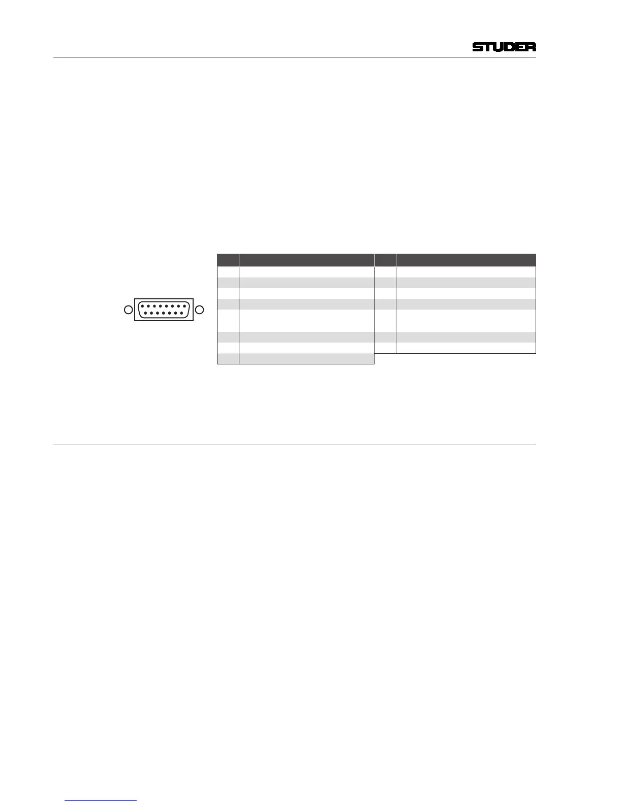
FAN/STATUS Connector (15-pin D-type, male, UNC 4-40 thread)
Pin Signal Pin Signal
1 +V
cc
(fan supply, +15...24 V) 9 GND
2 n.c. 10 n.c.
3 GND 11 reserved (NTC)
4 n.c. 12 n.c.
5
Alarm relay + (open collector,
pulling up to V
cc
if alarm triggered)
13 GND
6 n.c. 14 n.c.
7 GND 15 reserved (Alarm LED+)
8 n.c.
Replacement Fan: Order no. C072.010117
3.8 D21m I/O Subsystem
The D21m I/O system consists of various different analog and digital I/O
cards, general-purpose I/O cards, and cards for serial control. It is described
in a separate brochure (order no. BD10.275102).

 Loading...


