SCore Live
SCore Live 7Date printed: 28.02.11
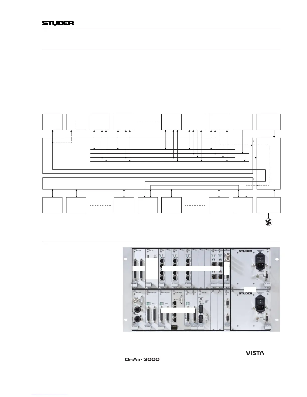
2.1 Block Diagram
The upper part of the frame houses the DSP section. Its backplane contains
four buses, as shown below:
TDM Bus Time Division Multiplex bus for audio and control data transfer between DSP
and bridge cards
Sync Bus Transport of sync signals between Ext. Sync card and Bridge cards
System Clock Bus Internal synchronization bus
I
2
C Bus System monitoring (card detection, monitoring of local voltages and tem-
peratures).
PWR
SEC.
PSU
PWR
*
*
for OnAir 3000 operation only
24 V
24 V
SCoreie
ACPA E
OS
CAR
OA3
or
2 ACPA E
PO CAR
O Slot O Slot ...2 2...
PO
CAR
Vita
SP CAR SP CAR SP CAR
E.
S C
CAR
PRAR PSU
CAR
RS422
ERER
CAR
PRAR PSU
AUO O
CAR
AUO O
CAR
AUO O
CAR
AUO O
CAR
AUO O
CAR
Syte Clo
Syn
2
C
SP CAR or
RE CAR
renant
RE
CAR
atie
2
C
A CORO
V3.0 an p
2.2 The Frame and its Cards
GPIO
Signal Processing (DSP)
Audio In/Out
Sync
PSU
GPIO
(Vista)
or
HOST
(OA3k)
123456 910111278
As illustrated above, an SCore Live frame houses up to nine DSP cards in the
center of the upper frame section. It also holds up to two ( ) or one
( ) additional D21m GPIO card(s) at the left of the DSP cards.
The lower section is reserved for D21m audio I/O and GPIO cards (described
in a separate D21m Product Information brochure).

 Loading...


