SCore Live
4 SCore Live
Date printed: 28.02.11
Ventilation Implementation A power dissipation estimation, considering the number of cards and their
conguration within the frame, is strongly recommended. The following
tables give some guidelines.
Card No. Card Name/Description
Dissipation
(approx.)
Backplane with power supply 10
W
DSP cards:
A943.0326 Host card 10 W
A943.0331 Ext. Sync card 0.2 W
A943.0360 DSP Pro card 11 W
A943.0370
B
ridge card (Redundant versions: A943.0370.35 and up)
11 W
D21m I/O cards*:
A949.0427 Mic/Line in card 11
W
A949.0428 Analog insert card 2
W
A949.0421 Line In card 7
W
A949.0420 Line out card 7
W
A949.0422 AES/EBU card 3.5
W
A949.0423 AES/EBU card with input SFC 4.5
W
A949.0424 AES/EBU card with input/output SFC 5.5
W
A949.0430 MADI card 4.5
W
A949.0425 ADAT card 1.7
W
A949.0429 ADAT card, long-distance option 1.7
W
A949.0426 TDIF card 1
W
A949.0412 HD card 5
W
A949.0411 MADI HD card 5.5
W
A949.0437 Serial card 0.2
W
A949.0438 Serial Merger card 0.6
W
A949.0435 GPIO card 3
W
* For more information on the D21m I/O cards, please refer to the separate
D21m Product Information brochure.
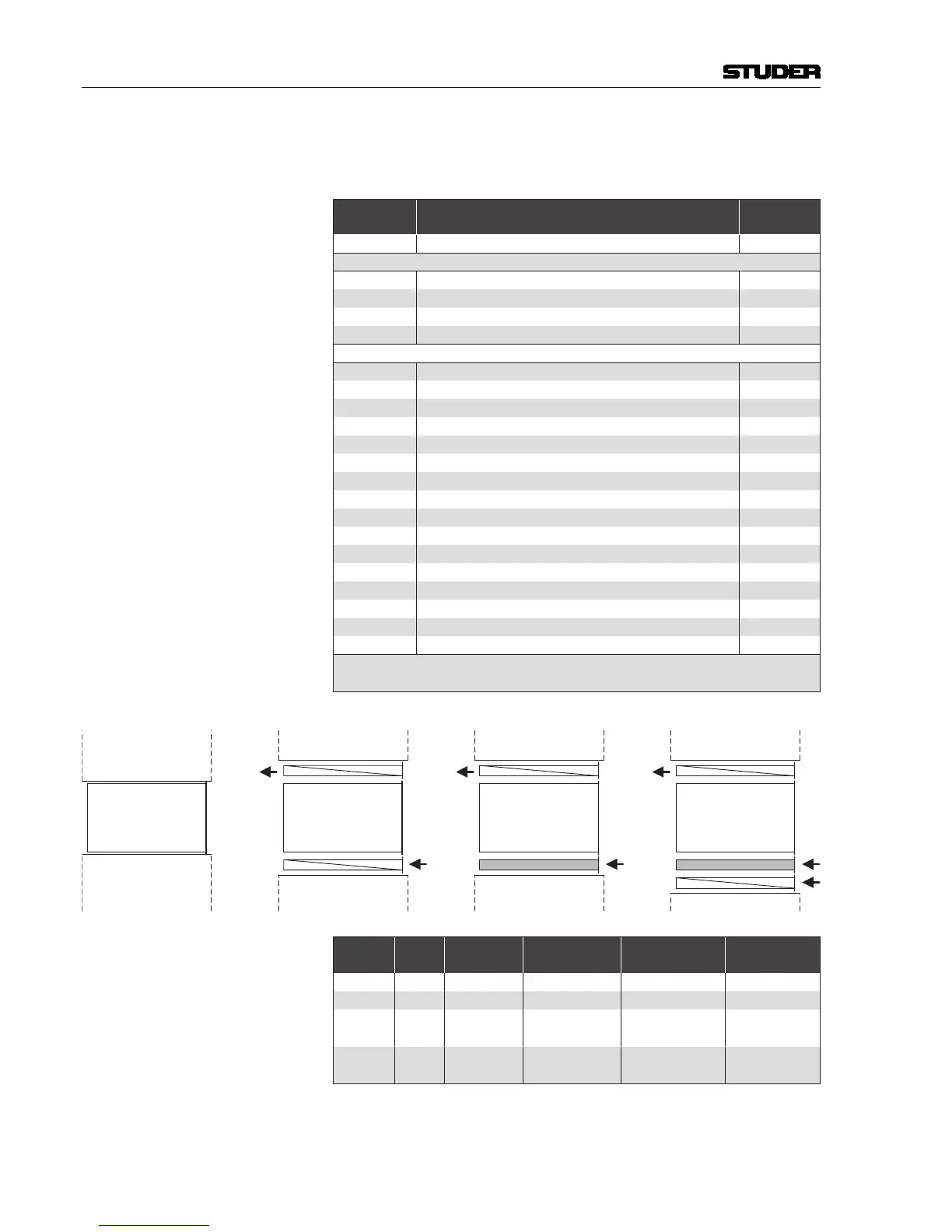
Setup A: Closed Setup B: Passive,
2 Air Deflector Units
Setup C: Active, 1 Fan
Unit, 1 Air Deflector Unit
Rear Rear
Air
Air
Air
Air
RearFront Front Front
Setup D: Active, 1 Fan
Unit, 2 Air Deflector Units
Air
Air
Rear Front
Core ive Core ive Core ive Core ive
Thermal
Setup
Total
Height
Max.
Dissipation
Restrictions Bottom Cooling Top Cooling
A
6 U 50 W - - -
B
8 U 100 W - Deector Unit Deector Unit
C
8 U 150 W
Cong. N1...N4
(see below)
Fan Unit Deector Unit
D 9 U 400 W -
Deector Unit
+ Fan Unit
Deector Unit
If required, the air ow direction may be changed by reversing the deector
and fan units. However, air intake at the front and air outlet at the rear is the
recommended scheme.

 Loading...


