STULZ Ultra-Series Humidifier Controller
8 (August, 2013)
the Humidifiers in the second group are turned off and the
Humidifiers in the first group return to proportional control.
Rotation of which group is the lead group occurs as in the
Rotate mode.
2.6.8.3 Bank Select
Bank select is controlled by a digital input from an external
source. It selects which group will operate. The other group
does not assist. If customer provided, the bank select
control contacts must be sized appropriately. The contacts
must have a minimal rating of 24 VAC.
2.6.8.4 Proportional Humidifier/Duct Limitation
The Proportional Limitation option limits humidity production
of a group of Humidifiers based on humidity or dew point to
prevent condensation from forming on cold surfaces. For
example, Humidifiers that may be positioned near the
ceiling or floor of an AHU, where condensation may occur,
can be configured as a group with a threshold applied to
limit humidity production. In this case, the limited
Humidifiers will be in Group A (see Figure 6) and limited by
the Limit Sensors. Group A would be selected to be limited.
The Humidifiers in Group A and B operate up to their full
rated output capacity based on the demand for
humidification. As the user selected limit humidity or limit
dew point temperature limit set point is reached, the
Humidifiers in Group A start scaling output back humidity
output proportionally until it is zero output. Limitation can be
set for either Group, but based on only one limit sensor.
The enables for Proportional limitation are set in the Service
Option Loop>Startup Menu.
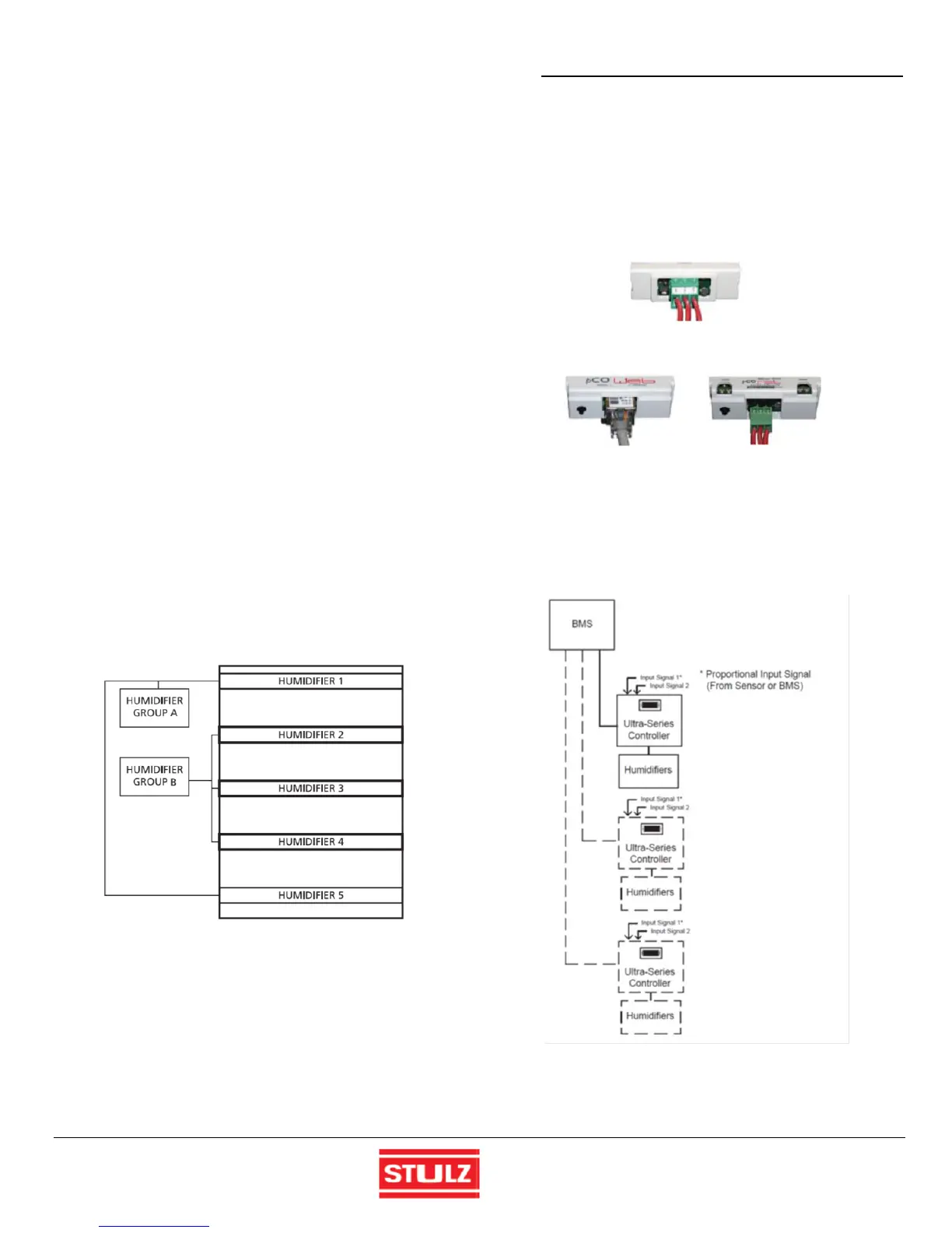
Figure 6- Humidifier Grouping
BMS Operation
2.6.9
The Ultra-Series controller may be equipped with a serial
communication port (Figure 7) that can be interfaced to a
Building Management System (BMS) via Modbus, BACnet,
SNMP or HTTP protocol as configured by the factory. A
controller interfaced to a network must be configured for
BMS communication.
Multiple Humidifier controllers can be connected to a BMS or
central control terminal allowing the communication of data
and information to the BMS. Instead of sensors, control
signals from an Ethernet interface may be used to mimic
sensors used by the Ultra-Series controller to manage
humidity levels. The controller develops and transmits
control output signal(s) to the Humidifiers based on those
input signals.
Modbus RTU
BACnet IP, BACnet Ethernet BACnet MS/TP
HTTP, SNMP & Modbus IP
Figure 7 - Serial Interface Ports
Each controller added to the network must be configured for
BMS communication and assigned an address.
Figure 8 - Supervisory Control of Humidifiers

 Loading...
