STULZ Ultra-Series Humidifier Controller
12
(Augu
st,
201
3)
4.0 OPERATION
4.1 General Theory of Operation
This Ultra-Series controller is designed to control the output
of an ultrasonic humidification system in a space or process
application to humidity levels as defined by the user.
Humidified air is supplied to the conditioned space as
needed to maintain the relative humidity or dew point
control set point. The controller may also be networked with
a group of Humidifiers to manage their outputs as a system.
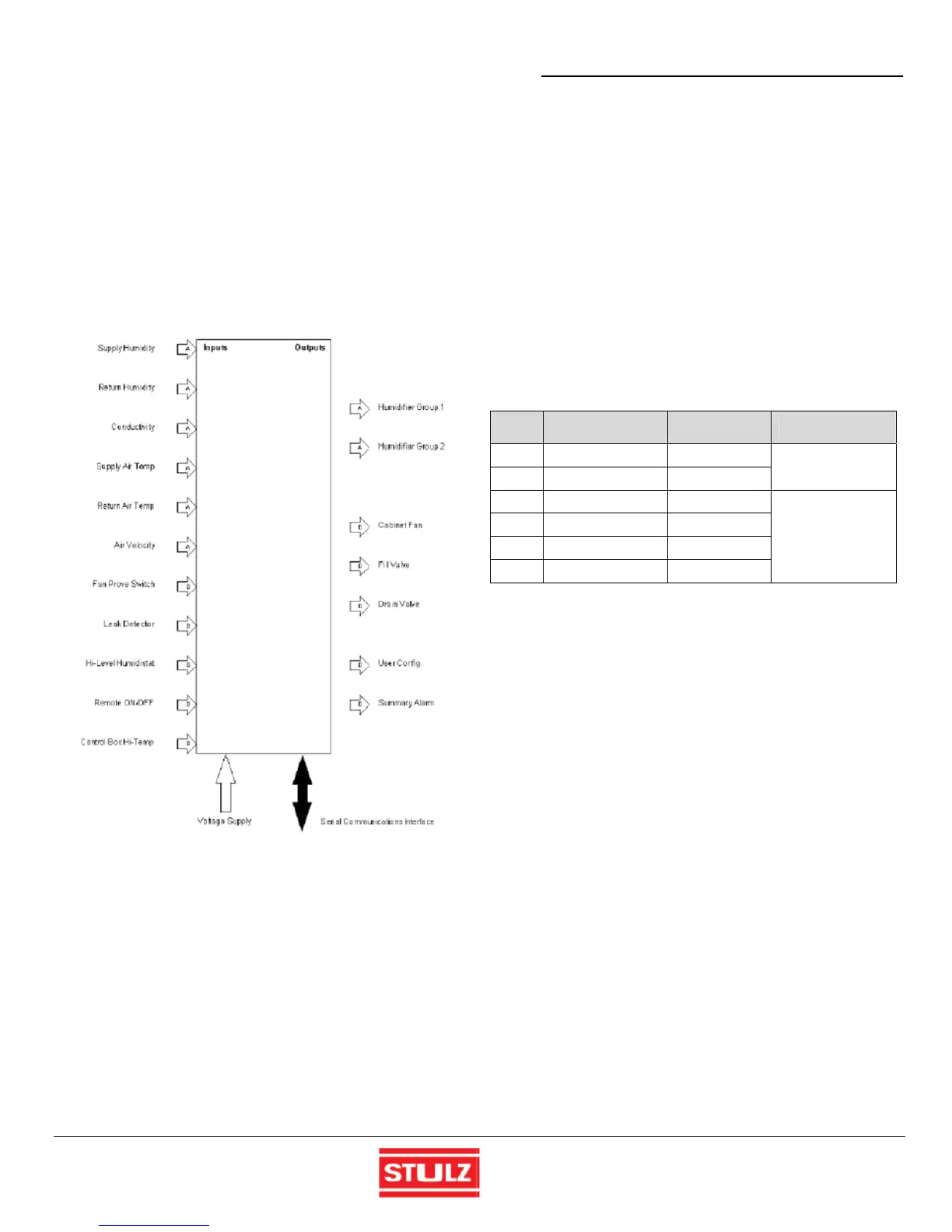
The controller I/O module includes inputs and outputs as
depicted in Figure 11:
Figure 11 - Control Inputs and Outputs
Humidification Control
4.1.1
The method of operation depends on the controller's
programmed operating mode. Control takes place by
means of the controller analyzing signal inputs from
sensor(s) and/or from an external supervising controller or
Building Management System (BMS).
4.1.1.1 Humidity Control
The controller responds to relative humidity sensor signal
input(s) to manage humidity production against a relative
humidity control set point.
4.1.1.2 Dew Point Control
The controller calculates dew point based on signal inputs
from temperature and humidity sensor(s) to manage
humidity production against a dew point control set point.
4.1.1.3 Proportional Control
The controller uses an external input signal representing 0
to 100% output to control humidity production.
Operating Modes
4.1.2
There are 6 operating modes for the controller depending
on how many and what types of inputs are used. The
operating mode has been pre-set by the factory and should
not require adjustment. BMS Signal indicates the input is
sourced by the serial BMS interface. Sensor indicates the
input is a physical signal and may originate from a sensor
or a voltage/current generated by another control system.
Mode
Input 1
(Control)
Input 2
(Limit)
Function
1 BMS Signal None
Room Control
2 Control Sensor None
3 BMS Signal BMS Signal
Return duct
monitoring with
proportional high
limit
4 Control Sensor Limit Sensor
5 BMS Signal Limit Sensor
6 Control Sensor BMS Signal
4.1.2.1 Room
Control
The controller may be configured for room installations with
only one control input. In room installations the controller
maybe configured to manage humidity production based on
a control signal from a return air humidity sensor or
optionally from a relative humidity and temperature sensor
for dew point control or, a signal from an external controller
or BMS can be used (Modes 1 & 2).
4.1.2.2 Return Air Duct Monitoring (DAH Units)
When used for duct installed, DAH Humidifiers in air
handling units, two inputs may be utilized. Input 1 is the
control for the humidity in the return air duct and input 2 as
a proportional high limit signal downstream of the
Humidifier. The inputs may be from a BMS/external
controller and/or remote sensors (Modes 3 - 6).
 Loading...

