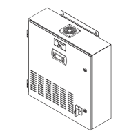
STULZ Ultra-Series Humidifier Controller
18 (August, 2013)
13. One to six hours may be required to see a desired level
or rise of humidity in the conditioned space. Once room
conditions have been programmed or set, a repeat visit
to the conditioned site may be required to ensure the
Humidifier is meeting the room's requirements.
Main Info Screen
4.4.1
See Note
See Note
The main information screen is displayed approximately 30
seconds after power is applied to the unit. The main screen
is a status screen displaying current system operating
information. See Section 5.2.1 for details on the fields in
this screen.
NOTE
The relative humidity (%Rh) is always displayed
but the current temperature (°F) and dew point (DP)
appear only if an optional temperature or dew point
sensor is provided. Operator interface to the menu
loops is available by pressing the “Prg” key. The
controller initiates a timer whenever a key
sequence is initiated. Every time a button is
pressed, the timer is reset. If there is no key activity
for two minutes, the controller will return to the Main
Info screen. The time delay is preset at the factory.
Saving & Restoring Set points
4.4.2
Upon initial start-up the system operates using the set
points programmed by the factory (Factory Parameters) as
the operating set points. As described in Section 4.4, steps
6 - 10, the customer may enter new operating parameters
in the Control the new set points in the Service menu if it is
intended to save them (Section 5.5.8). Once stored, the set
points now become the restorable Customer Parameters.
The Factory set points entered by the factory still remain
stored in the controllers' memory as the Factory
Parameters.
At any time, set points for the system may be re-adjusted to
any value and the system will operate accordingly. If it
becomes necessary however, the customer may enter the
Service menu and restore the set points to the stored
Customer Parameters values. The original Factory
Parameter values may also be restored from the Service
menu. Whichever set points are restored (Factory or
Customer); they become the current operating set points.
4.5 Controller Features
Alarms
4.5.1
As programmed into the system controller, an alarm
condition activates the summary alarm logic which
illuminates the alarm key and energizes an audible alarm (if
that option is selected). A message detailing the alarm
condition is displayed by pressing the alarm () key. Some
alarms are programmed by the factory to automatically shut
down the Humidifier until the alarm condition is remedied
and the alarm is cleared by pressing the alarm key. Alarms
that may be enabled by the factory are listed in Section 5.3.
4.5.1.1 Summary Alarm
A summary alarm will activate when the controller senses
any programmed alarm condition. This illuminates the alarm
key and activates an audible alarm. A summary alarm also
energizes Normally Open/Normally Closed summary alarm
contacts to remotely monitor alarms. If a Critical alarm
condition is detected, a summary alarm will be
accompanied by Humidifier shutdown.
4.5.1.2 Custom Alarms
A Custom Alarm (user configured) is activated upon
detection of one or more individual alarm conditions as
selected by the operator in the Service>Options>Custom
menu loop (see Section 5.5.4.3.2). When a custom alarm
condition is detected, the alarm key illuminates and a
designated set of N.O. & N.C. Custom Alarm relay contacts
are energized to provide remote indication of the selected
alarm condition(s).
For example, it may desired to have a remote notification
when a High Conductivity pre-alarm is detected, giving
notice that the mineral content of the supply water is
approaching an unsafe level. This gives an alert before the
mineral content of the water reaches the high conductivity
threshold and the Humidifier is shut down.
The controller may be factory configured to activate up to
four Custom Alarms. One user configurable Custom Alarm
with relay contacts is provided as a standard and up to
three additional may be provided as an option.
4.5.1.3 Customer Alarms
A customer provided digital (on/off switching) alarm sensor
may be connected to the terminals provided in the electric
box. This may be for any site specific alarm condition the
user wishes to monitor that may or may not be provided in
the standard alarms menu; i.e. gas detection, intrusion
alarm, etc. Upon detection of a customer alarm, the alarm
key illuminates and the alarm display screen provides a
message indicating a customer alarm message. The screen
message "Customer Alarm 1" will appear (default) in the
controller display or the user may re-configure the controller
to display any alpha-numeric message desired, up to 20
characters long, in the Service>Options>Custom Setup
menu loop (see Section 5.5.4.3.1). One Customer alarm
(Date) (Time)
00.0°F
00%Rh
100 100 Dp 00.0°F
Unit On
Grp A On Grp B On
←
←

 Loading...