STULZ Ultra-Series Humidifier Controller
(August, 2013) 5
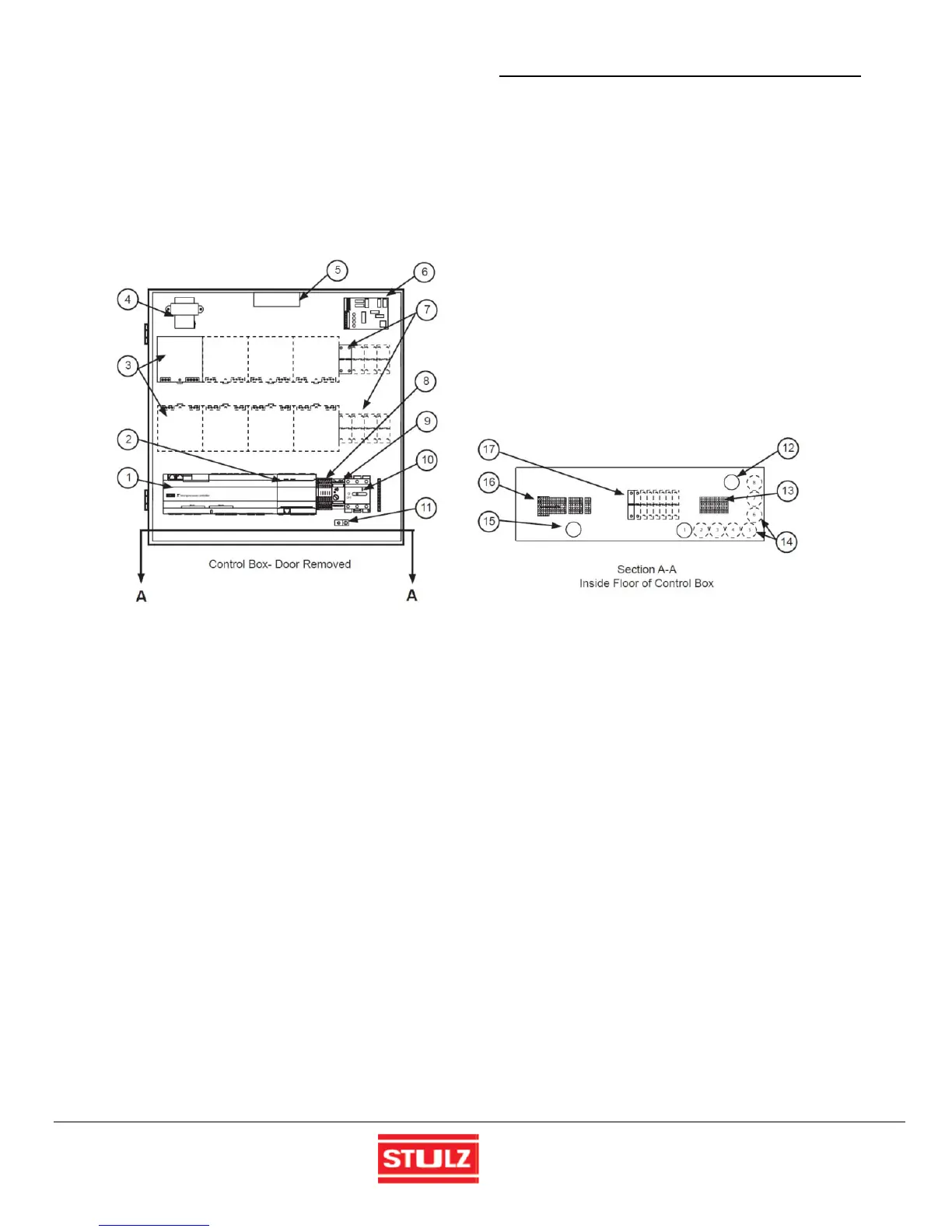
2.4 Controller Nomenclature
The Ultra-Series controller box contains the main operating components. The control box layout, shown in Figure 3, is a
typical layout showing power supplies for up to eight individual Humidifiers. One power supply is provided for each
Humidifier to be controlled. The higher the Humidifier capacity is, the larger the power supply for it must be. Depending on
the number of Humidifiers that need to be controlled (up to 16), the number of power supplies required may not fit inside
the Ultra-Series enclosure. In that case auxiliary control boxes are utilized to house additional power supplies as needed.
Figure 3 - Control Box Internal Layout
The item numbers below coincide with the call outs in Figure 3.
1. Controller I/O module (Figure 4)
2. Expansion I/O module (for conductivity sensor)
3. Humidifier power supplies (8 maximum)
4. Controller transformer
5. Vent Fan
6. Sensor averaging board (optional)
7. Power supply circuit breakers (8 maximum)
8. Humidifier output relays
9. Water detector control module (optional)
10. Service disconnect switch (*see note)
11. Cabinet ground lug
12. Knock-out for power cable
13. Humidifier(s) output terminal block
14. Knock-outs for Humidifier cables (8 max)
15. Knock-out for control wires
16. Control interface terminal blocks
17. Humidifier circuit breakers (8 maximum)
*Note: The service disconnect switch removes power from the Ultra-Series controller and only the Humidifiers connected
directly to it. Auxiliary boxes power the Humidifiers they are connected to, but the Humidifiers will time out and shutdown if
the control signal is interrupted by turning off the Control Box disconnect switch or if the control signal is lost over the
Modbus. Auxiliary Boxes must have their service disconnect switch turned off to stop the operation of the Humidifiers
connected to them while other Humidifiers are continuing to run off the Control Box and other Auxiliary Boxes.

 Loading...
