STULZ Ultra-Series Humidifier Controller
10 (August, 2013)
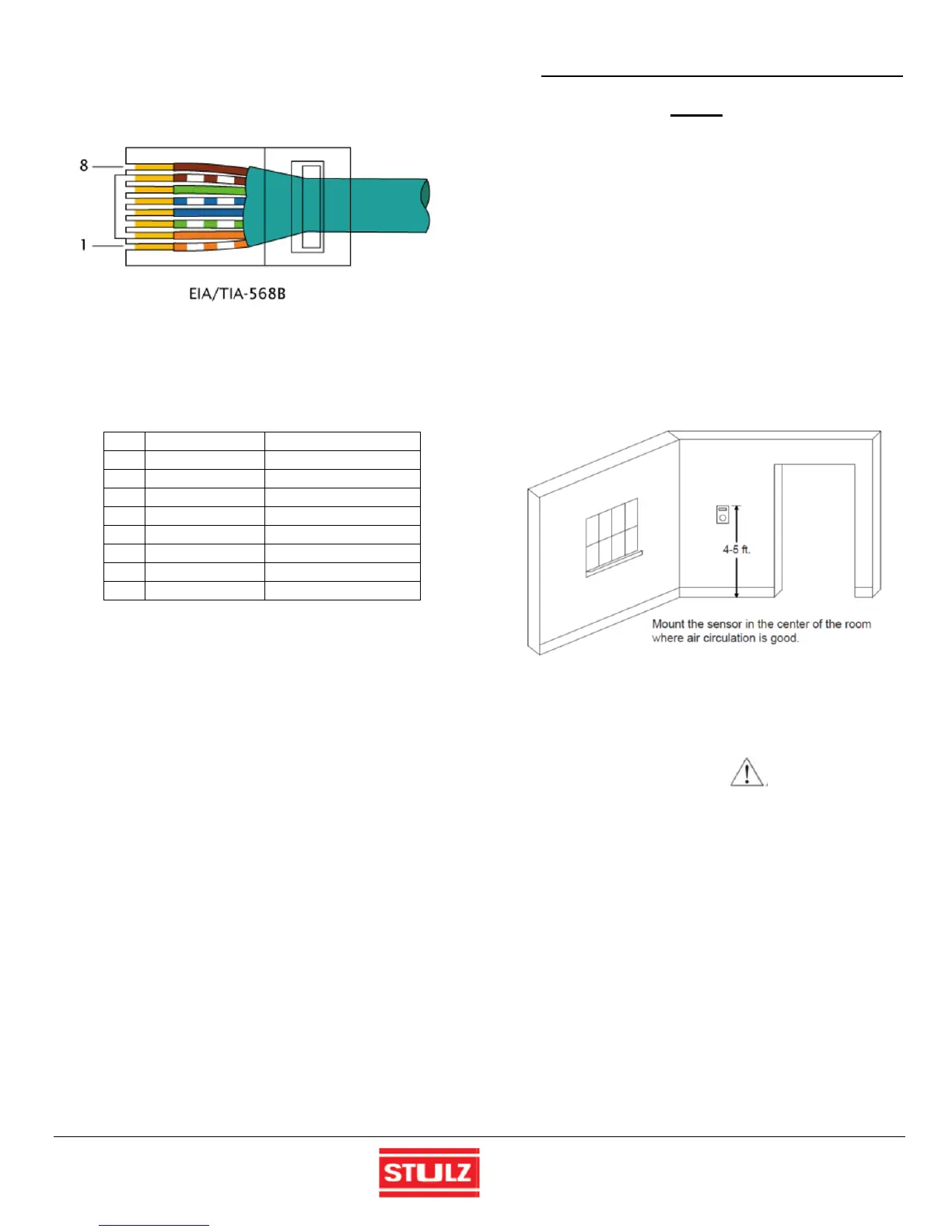
EIA/TIA-568B wiring Standard shall be used. Figure 9 is the
pin side of the connector (tab on the other side).
Figure 9 - RJ45 Connector
A Jack is mounted in the control box to connect to the
humidifiers. The wires marked Shield are not connected to
the humidifiers, but passes through all units as a generic
shield. It is connected to chassis ground in the Control Box.
Pin Color Name
1 Orange/White DC Ground
2 Orange DC Ground
3 Green/White RS-485 +
4 Blue RS-485-
5 Blue/White RS-485+
6 Green RS-485-
7 Brown/White Shield
8 Brown Shield
Sensors
3.3.4
The Ultra-Series control box is equipped with a terminal
block for the connection of a humidity sensor and/or an
optional temperature/humidity or dew point sensor. A
sensor/transmitter is required regardless of the control
mode selected. If provided by STULZ, sensors and
transmitters are shipped loose for installation by the
customer. Interconnecting field wiring should be installed in
accordance with NFPA 70 of the National Electrical Code
(N.E.C.). The wiring connections for sensors must be made
using shielded cable with a minimum AWG 22 (0.5 mm
2
cross section) for each lead. Trim the length of the sensor
cables where possible to minimize wire resistance and
avoid wrapping the cable around power devices.
A remote sensor must be located so that it will properly
sense the conditions to be controlled. Refer to Sections
3.3.4.1 or 3.3.4.2 when mounting sensor(s). Refer to Figure
3 for the location of the controller interface terminals and to
the electrical drawing for wiring details.
NOTE
All wiring should conform to local and national
electrical code requirements. Use of copper
conductors only is required. Wiring terminations
may become loose during transportation of the
equipment. Therefore, it is required to verify that all
wiring terminations are secure.
3.3.4.1 Room Temperature/Humidity Sensors
Mount a room control sensor/transmitter in the center of the
room where air circulation is good. The sensor should not
be mounted near a doorway or an area where it would be
exposed to direct sunlight. Wall-mounted control devices
should typically be mounted 4-5 feet up from the floor in the
conditioned space (see Figure 10). Care should be taken
not to install the sensor in an area with excessive changes
in humidity and temperature.
Figure 10 - Locating Wall Mount Sensor
Make the wiring connections to the controller interface
terminal block as shown in the electrical drawing(s).
CAUTION
Do not damage the exposed temperature/humidity
sensors on the PC board while screwing in the
cover fastening screw. The circuitry can be
damaged if handled improperly.
3.3.4.2 Duct Mounted Sensors
Cut a hole in the side of the duct and mount the sensor,
(temperature, humidity and or air velocity) to the duct using
the screws provided. Position the supply air sensors
approximately 10 feet down stream of the Humidifier outlet.
Each supply air sensor is to be field connected to the
controller at the terminal positions designated in the
electrical drawing.
Water Conductivity Probe
3.3.5
The Ultra-Series control box monitors water quality via a
probe (sensor) shipped loose. It is to be field installed in the
 Loading...

