INSTALLATION, OPERATION, AND MAINTENANCE MANUAL
8 SUMMIT PUMP MODEL CCFM GENERAL PURPOSE
6 INSTALLATION
6.1 GENERAL
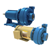
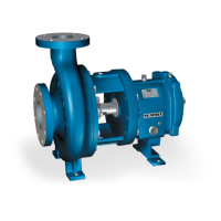
Summit Pumps are assembled at the factory. The pumps are ready to be installed and put into
service. Follow all instruction tags on the pump. Ensure all fluid properties and application
requirements have been considered and relayed to manufacturer and/or distributor. Suction piping
should be as short and direct as possible.
6.2 LOCATION
If the pump is going to have a water flush, it should be located as close as possible to the supply of
water. Other location considerations are: easy access for inspection, maintenance and ample
overhead space for lifting with crane or hoist.
6.3 BASE PLATE
Each pump unit should be mounted on a fabricated steel base plate. The base plate should be
mounted on a concrete sub base 4” to 8” longer and wider than the fabricated base plate.
6.4 FOUNDATION
Use a foundation that is sufficient enough to support all points of the pump base-plate. Level and
grout the base-plate per standard construction practices.
6.4.1 Concrete Sub-Base
The concrete sub foundation performs a number of functions. It must support the weight of the
entire pump assembly, maintain the alignment of all system components, and absorb the loads,
forces and vibrations that are developed under normal operating conditions. The concrete material
used must be top quality and conform to local building codes as well as the contractor’s strength
requirements. Reinforcing bars and mesh should be used as required. The mounting surface of the
concrete foundation must be flat and level beneath the footprint of the sub-base, or the pump could
be installed out of square. This could create problems aligning the piping, place extra loads on the
couplings and bearings, and alter the operating levels of lubricants or hydraulic fluids in the
system. It is recommended that the top surface of the slab be held flat and level to at least F50
according to American Concrete Institute (#117) and the Canadian Standards Association
(#A23.1) which is approximately 1/8” per 10 foot. The sub base height is usually determined by
the process piping runs and elevation.
The weight of the sub foundation should be 3-5 times the weight of the pump, motor and
baseplate. Dimensionally, it should be 4” to 8” longer and wider than the polymer concrete or
fabricated steel base plate. Anchor bolts are installed in pipe sleeves. The pipe diameter is 2.5
times larger than the anchor bolt diameter. This sleeve/bolt assembly is embedded in the base
when poured.
The pipe sleeve should be filled with sand or plastic foam to the top of the sleeve. This will
prevent the grout material from spilling into the sleeve and reducing the movement of the sleeve
when pouring the grout.
Anchor bolt sizes: 1”-8UNC. Length is 7.5” to 10”, depending on base thickness and overall size.