INSTALLATION, OPERATION, AND MAINTENANCE MANUAL
SUMMIT PUMP MODEL CCFM GENERAL PURPOSE 21
11 DISASSEMBLY MODEL CCFM
This section will cover sizes: FM1, FM2, CC1 and CC2 in Cast Iron/Bronze and Stainless
construction. It must be noted that although there are slight differences within these options, the
disassembly and assembly procedures follow the same progression. Use the following steps as a
general guideline, as it is impractical to cover every situation.
Refer to section 10 EXPLODED VIEWS, on pages 17 through 20 for part item numbers and images.
When item numbers are called out in this manual, they will be in parentheses following the
description of the part. Example: Casing (01).
Notes:
• Cast Iron/Bronze construction will have casing rings (07) and in some pump sizes adaptor
rings (27). These are wearable items and can be replaced when worn. Stainless construction
will not have these rings as the adaptors (71) and Casings (01) are machined differently.
• Frame 1 (FM1 and CC1) in stainless construction will have a sealed shaft. This means there
are two extra parts from the Cast Iron/Bronze construction: Impeller Sleeve O-Ring (131)
and Gasket, Impeller Bolt (26A). These extra parts seal the shaft from the pumped fluid
protecting the steel shaft from any chemical corrosion.
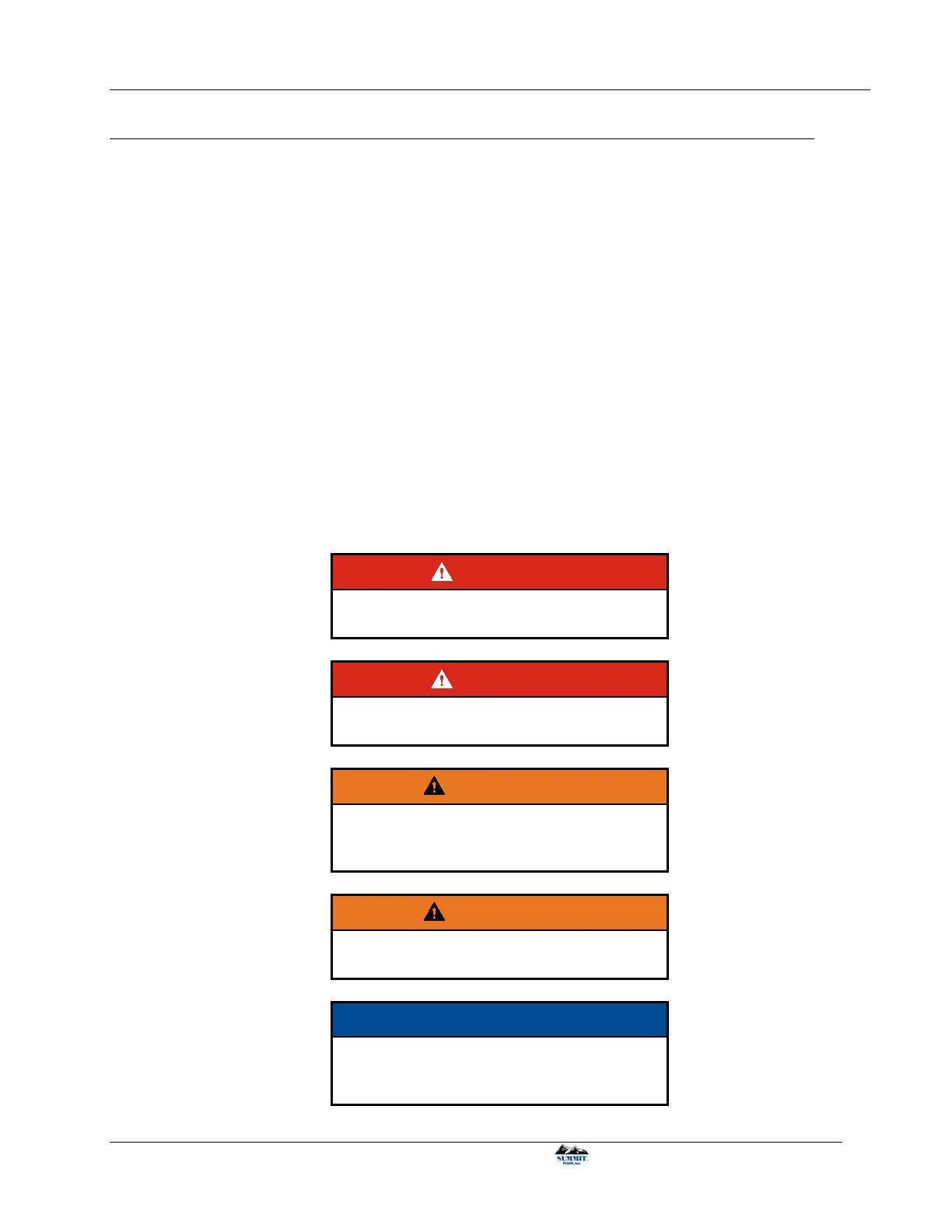
DANGER
Lock out power to avoid personal injury or
death when working on pump.
DANGER
Properly vent any pressure in pump, fittings
and connecting lines.
WARNING
Understand material being pumped. Obtain
MSDS information for product. Take all
necessary precautions.
WARNING
Wear eye protection and proper personal
protective equipment.
NOTICE
Secure pump before disassembly to avoid
damage. Pump’s center of gravity changes
when removing parts.