16
High voltage existing in the AC power supply port. Do not operate
under voltage. Make sure the input side is completely voltage-free and
check to make the ground cable is reliably grounded before cable
connection.
SD card does not support hot plug.
6.3 Connection to PV System Devices
The devices in the PV system that can connect to the Logger3000 are: inverter,
EM device, transformer, power distribution cabinet, meter and etc. as the input
of the Logger3000, the connection method is shown below.
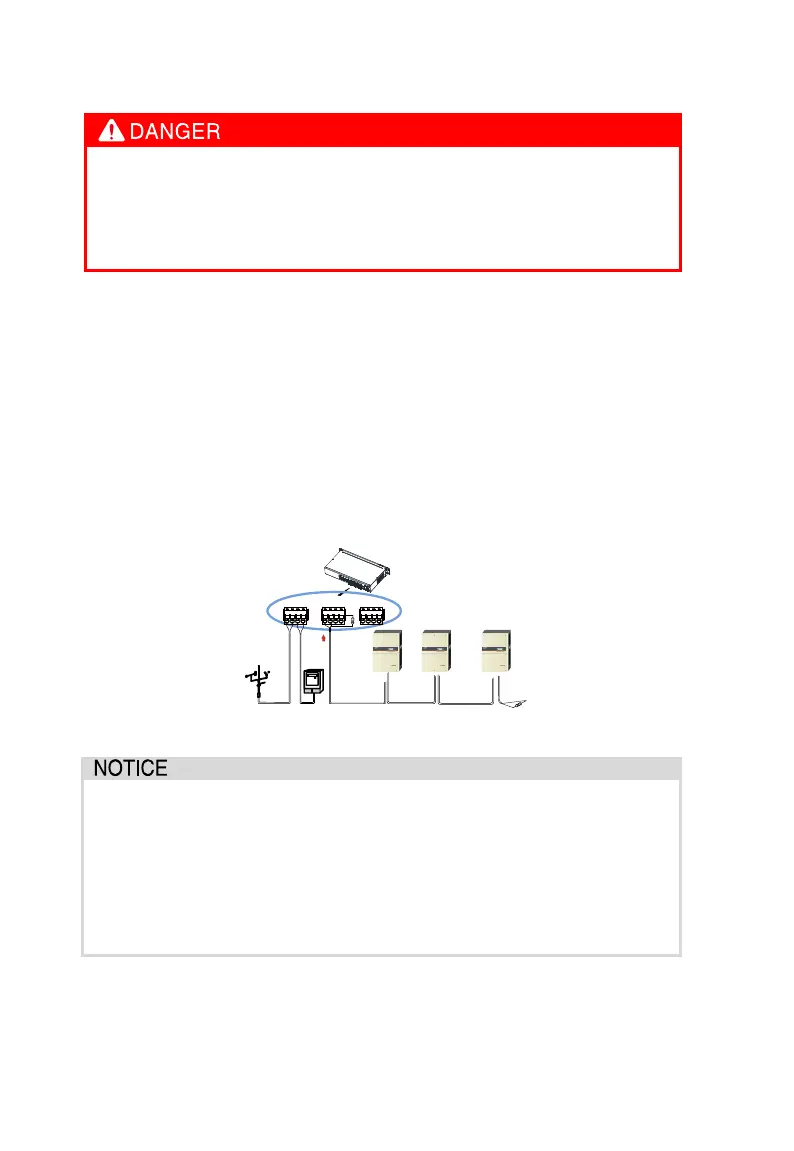
6.3.1 COM Port Connection
Several EM devices and etc. connect to the Logger3000 in RS485 daisy chain.
When the meter connects to the Logger3000, the communication protocol
should meet the DL/T645-2007 requirement.
Inverter 1
Logger
120Ω
EM
RS485 Daisy chain
Inverter
2
Meter
120Ω
A1 B2 A3 B3 A4 B4 A5B5 A6B1A2
B6
Inverter
n
RS485 communication cable must be shielded twisted pair cable and
single-point grounded.
The max. cross-sectional area of the shielded twisted pair cable should
not exceed 1.2mm² and should not be smaller than 0.2mm². the stripped
length of the cable is 8mm (recommended).
Keep at least 0.5m from the strong electricity; avoid parallel cable layout;
use the steel tube for area with strong interference.
Add a SPD if the external device connects to the Logger3000. The
Logger3000 may be damaged by lightning if otherwise.