14
6 Electrical Connection
6.1 Safety Instructions
Incorrect cable connection may damage the Logger3000 and even the
operator.
All cables must be intact and well-insulated. The dimensions are
proper and the connection is secure.
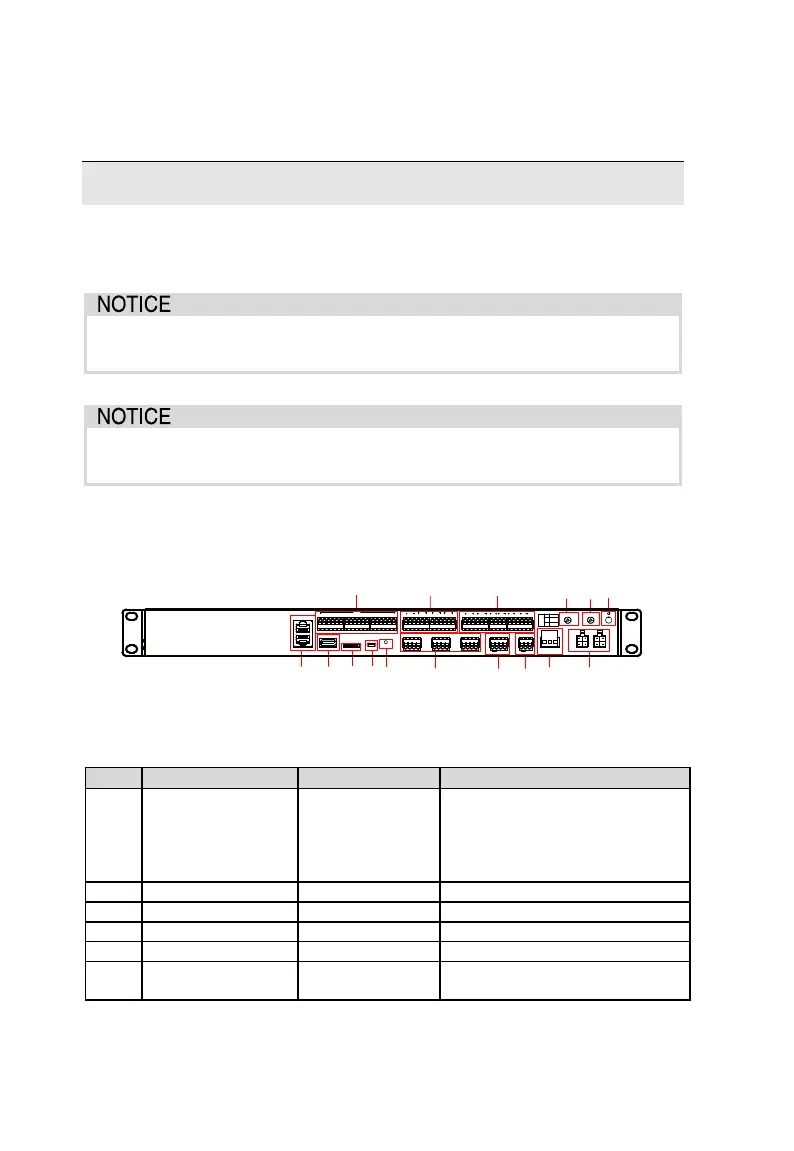
6.2 Terminal Introduction
A
B
C D E
G H
I LJF K
M N O
P
ETH2
ETH1
USB SD Debug RST
0V 1 2 3 4 5 6 7 8 9 10 11 12 13 14 1516 0V
DIN
1 2 3
DO1
1 3
DO2
1 3
DO3
1 3
DO4
2 2 2
A1B1 A2 B2 A3B 3A4 B4 A5B5 A6B6
+ - GND
PT1
+ - G ND
PT2
+ -
AI1
+ -
AI2
+ -
AI3
+ -
AI4
H L
CAN
+ -
24V
AC(L) AC(N)
GPS/BDS RF
L1 L2
DO
1
2
3
NO
NC
COM
Identify the cable connection terminals according to the table below before
cable connection.
Tab. 6-1 Terminal description
ETH2 can connect to the
background master station
through the switch, router or
other devices. Function of ETH1
is reserved
Used to debug the Logger3000
Used to reset the hardware of
the Logger3000