S
S
S
R
R
R
F
F
F
6
6
6
1
1
1
8
8
8
B
B
B
6
6
6
U
U
U
s
s
s
e
e
e
r
r
r
’
’
’
s
s
s
M
M
M
a
a
a
n
n
n
u
u
u
a
a
a
l
l
l
~32~
Chapter 7 Pre-monitoring Preparation
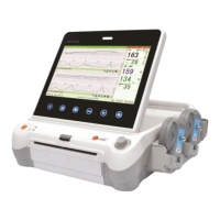
7.1 Switching On
WARNING:
1) Check if all the metal parts are linked to the protective earth cord and the cord is in good condition
before switching on the monitor.
2) If any sign of damage is detected, or the monitor displays some error messages, do not use it on any
patient. Contact biomedical engineer in the hospital or our service engineer immediately.
Press the POWER key on the top panel to switch on the monitor. The power indicator lights up and a start-up
music will be heard. You can operate the monitor after the main interface appears.
NOTE:
Make sure the paper is correctly loaded before the printing starts.
7.2 Adjusting Screen Angle
The angle between the screen and the top cover of the monitor is adjustable as needed, allowing it to be
mounted on a wall or placed on a flat surface.
Adjustment method:
Push the hook on top of the screen left to spring it open. Pull the screen forward to adjust to one of the preset
screen angles. To bring the screen back to flat, pull it all the way forward and then push it back.
7.3 Setting Date and Time
You can change the date and time of the monitor, please refer to section 6.1 16) Time settings for setting the
date and time.
CAUTION:
You should set date and time information in advance. After this information is changed, the monitor starts
new monitoring with an auto ID. Therefore, we advise you to restart the monitor after changing date or time
information, and do not perform this operation when monitoring is in process.
7.4 Connecting Transducers
Check for visible damages of the transducers every time before connecting them to the monitor.
Pay special attention to the cracks on the transducers and cables before immersing them into conductive fluid.
If damage is found, replace them with good ones at once.
When plugging transducers into the monitor, make sure the arrow symbol of the connector faces up and put it
into the socket. The connection of the transducer(s) is one-to-one correspondence. If a transducer is inserted
to a wrong receptacle, it cannot be connected correctly.