S
S
S
R
R
R
F
F
F
6
6
6
1
1
1
8
8
8
B
B
B
6
6
6
U
U
U
s
s
s
e
e
e
r
r
r
’
’
’
s
s
s
M
M
M
a
a
a
n
n
n
u
u
u
a
a
a
l
l
l
~9~
2.4 Accessories
The accessories should be connected to the monitor via the sockets on the left side and right side panels.
Each accessory has a tab on the connector housing to ensure proper insertion into the appropriate socket on
the monitor.
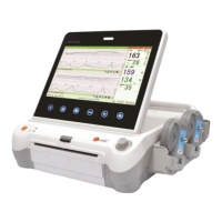
2.4.1 Ultrasound (US) Transducers
Fig 2-7: Wired US Transducer
Front view Back view
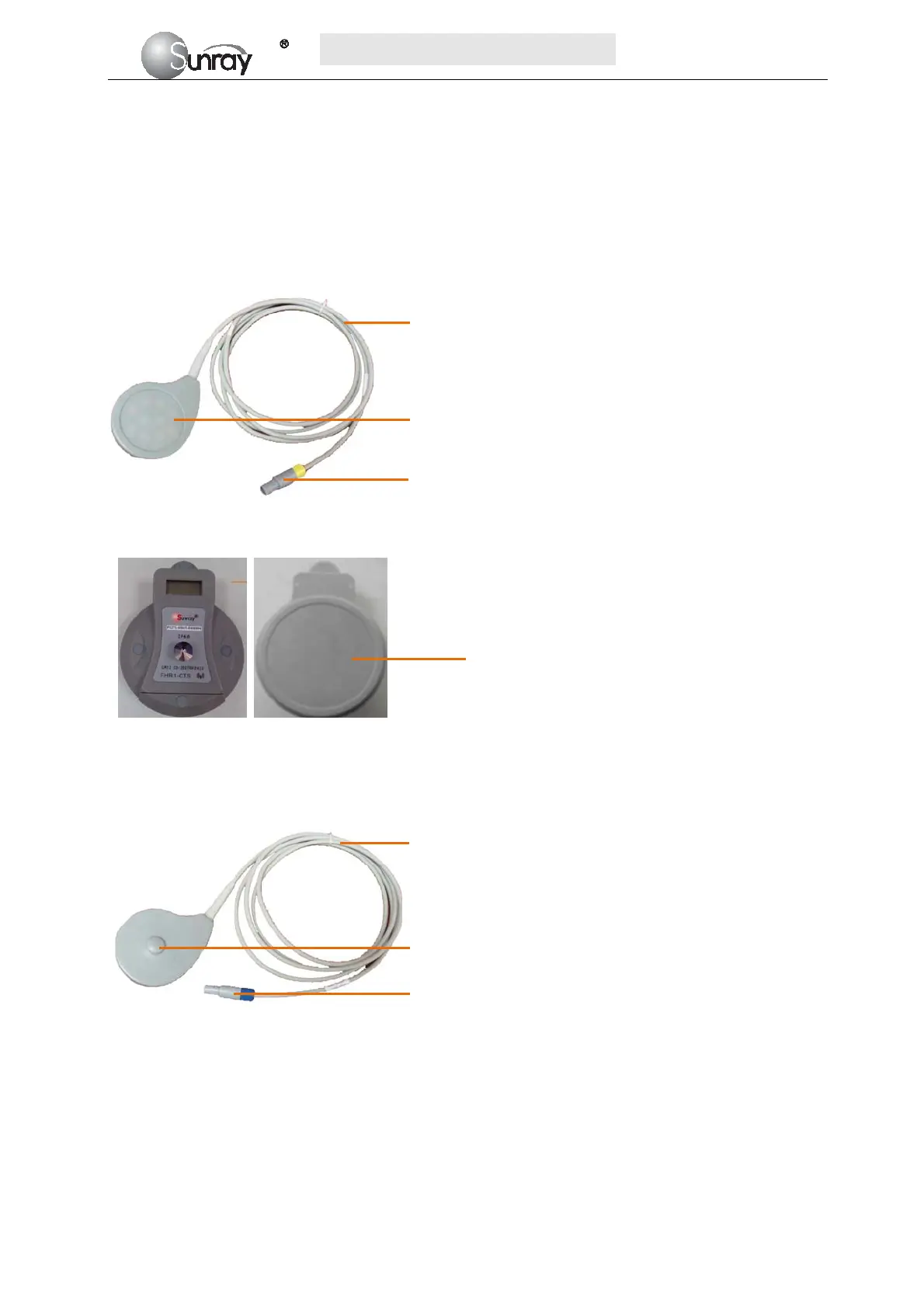
Fig 2-8: Wireless US Transducer
2.4.2 TOCO Transducers
Fig 2-9: Wired TOCO Transducer
1. Transducer cable
2. US Transducer Sensor
3. Transducer Connector
1
1. Transducer cable
2. TOCO Transducer Sensor
3. Transducer Connector
1
2
3
2
3
Wireless US
Transducer Sensor