25
10) Model of Transformer by Voltage and Setup of Voltage
A. Then inner structure is as below when the cover of electronically-controlled pattern sewing machine is removed.
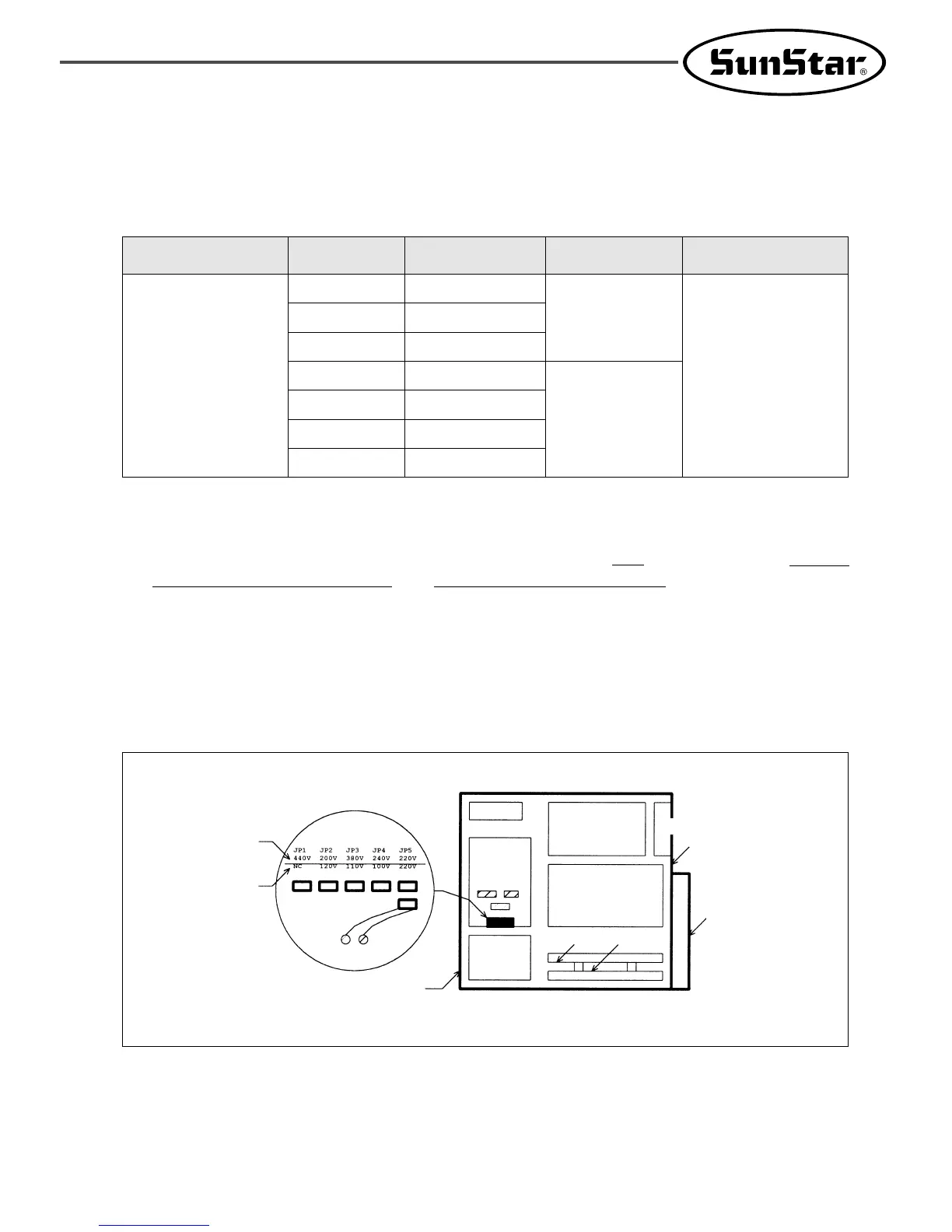
B. Confirm if the position of input vlotage change connector on power board (Refer Fig. 32) and used transformer are
properly selected according input voltage like Table 1
Model Input Voltage
Position of Input Voltage
Change Connector
Model of Used
Transformer
Reference
SPS/B(A)-1306
--
SPS/B(A)-1811
--
95V~105V
106V~115V
116V~125V
200V~230V
231V~245V
345V~415V
416V~480V
JP4
JP3
JP2
JP5
JP4
JP3
JP1
SPS/B(A)-1306-110
SPS/B(A)-1811-110
SPS/B(A)-1306-220
SPS/B(A)-1811-220
Control box is used only
for 1306 and 1811 diffe-
rently. You don’t need
differentiate it by elec-
tronic/pneumatic or
basic/perfect or general
use/thick materials acc-
ording to the model of
machine.
Table. 1 Model of used transformer and connector position according to input voltage
[ Fig. 32 Setup of Input Voltage Change Connector ]
Ex.) When model of machine is SPS/B(A)-1306--, and voltage is 220V, it is normal that the model of
used transformer is “SPS-1306-220 ”, and connector should be placed on “JP5”.
※ The model of transformer is attached to the upper transformer.
※ The trans for 1507 and 1310 is used in the same way of the trans for 1306.
C. Confirm if the power switch is for 3 phase or single phase.
D. If the setting of 2 and 3 is not proper, the machine can be damaged. In case, take below measures.
ⓐ Separate the connector linked to transformer from CN7, CN8, CN9 on power board.
ⓑ Fix the connector on any proper site on Table 1.
ⓒ Link the connector linked to transformer to the power borad.
Back side
Cable Cover of
Back Side
Front Cover
Main Shaft Motor
Drive Board
Step Motor
Drive Board
Fan
Power Board
CN7 CN8
CN9
Floppy
Disk
Driver
If an Input voltage
is more than 220V
If an input voltage
is more about 110V
Main)
Transformer
IO Board CPU Board
 Loading...