40
17) Mounting the Direct Motor and Adjsuting
Method(B Series)
A. When you mount the coupling on the servo-motor, fit
the screw No.1 of coupling to the flat surface of the
servo motor shaft and make the clearance between
the coupling and servo motor 0.7mm.
B. When you mount the coupling on the upper shaft, fit
the screw No.1 of coupling to the flat surface of the
upper shaft and make the clearance between the
coupling and upper shaft bushing(R) 2mm.
C. After mounting both couplings, check the positions of
each screws to the aligned.
※ If the positions of each screws are not aligned, the
needle does not stop normal position.
[ Fig. 66 ]
Upper Shaft
Rear
Bushing
Upper Shaft
Servo Motor
Coupling
Flat Surface
Screw NO.1
0.72
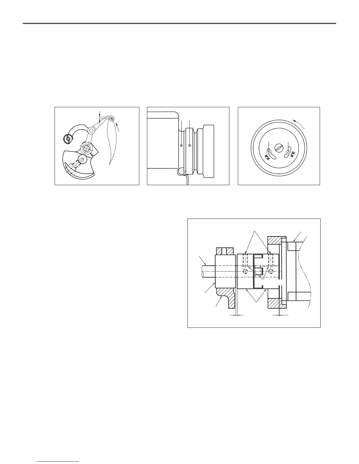
B. Adjusting the position of position detector
ⓐ Adjust the position of take-up lever to be same as Fig. 63 by turning the pulley. At this time, the white carving
sign of pulley should be straight line with the carving sign of arm.
ⓑ Unfasten the screw ① on the N.U carving sign of pulley to be located on the center of space, and fasten the
screw again.
ⓒ Unfasten the screw ② on the N.D carving sign and move to the right and left, then let it suspend on the place
where the needle bar just start ascending from the bottom.
[ Fig. 64 ]
[ Fig. 63 ]
Direction
of Rotation
About 3mm
[ Fig. 65 ]
Direction of
Rotation
①②
 Loading...