17
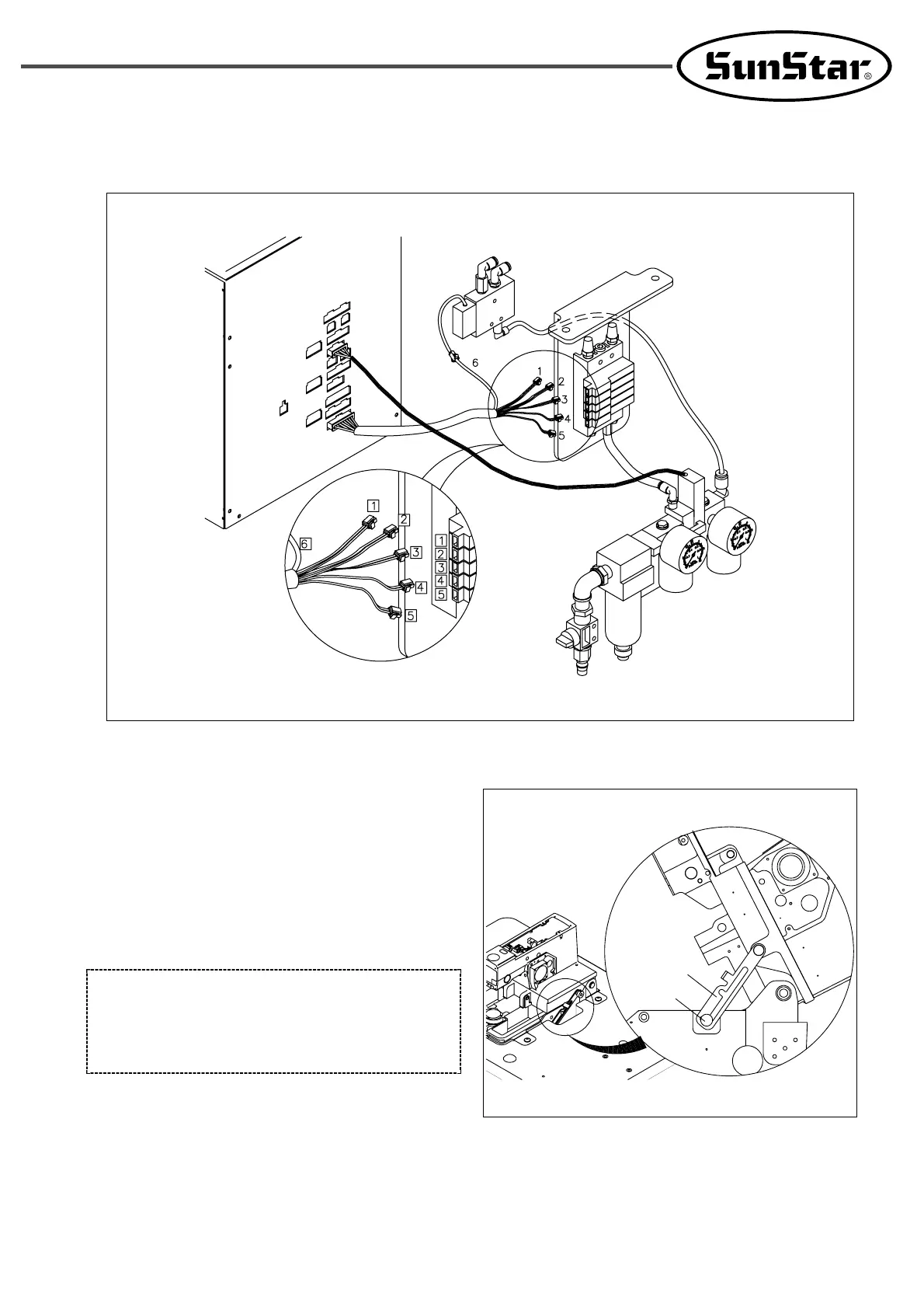
[ Fig. 9 ]
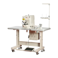
6) Connecting cables to control box
A. Lift the machine as much as possible as in the figure and
make the head supporting lever axis (B)① inserted into
the groove of the head supporting lever②.
①
②
[ CAUTION ]
When lifting the machine, make sure that the head
supporting lever axis(B) is inserted into the head
supporting lever groove.
[ Fig. 8 ]
D. Connect cables, which are linked to the control box, to solenoid valves according to each number .
Control box
 Loading...