EasyManua.ls Logo

SunSynk HV Series - User Manual

SunSynk HV Series
49 pages
Print Icon
To Next Page IconTo Next Page
Loading...
HIGH VOLTAGE SERIES
LI-ION RACK MOUNT SYSTEM
v.18 (10/18/23)
HIGH VOLTAGE BATTERY
INSTALLER MANUAL
PLEASE RETAIN FOR
FUTURE REFERENCE
www.sunsynk.com
sales@sunsynk.com
customerservices@sunsynk.com

Table of Contents

Question and Answer IconNeed help?

Do you have a question about the SunSynk HV Series and is the answer not in the manual?

SunSynk HV Series Specifications

General IconGeneral
Nominal Voltage51.2V
Usable Energy4.6kWh
DOD90%
Capacity (kWh)5.12 kWh
Voltage Range44.8V-57.6V
CommunicationCAN/RS485
Operating Temperature-10°C to 50°C
ProtectionOver Current, Short Circuit, Over Temperature
ChemistryLiFePO4

Summary

IMPORTANT INFORMATION

Scope and Specifications

Details manual applicability, HV-Series Set specs, symbols, and warnings.

General Safety Information

Disclaimer

States Sunsynk Ltd.'s liability limitations for product use and maintenance.

Proper Use

Defines conditions and restrictions for installing and operating the system.

SAFETY

Safety Rules and Information

Lists rules and provides instructions for safe operation of hazardous parts.

Requirements for Installation Personnel

TRANSPORT TO THE END CUSTOMERS

Provisions on Shipping of Battery Modules

Details regulations and provisions for shipping lithium-ion products.

PREPARATION

Tools Required

Lists the tools necessary for installation and their uses.

DESCRIPTION AND INSTALLATION

Installation Precautions

Warns about potential building damage from static overload and site selection.

Product Description

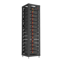
Describes the High Voltage Series Battery system, features, and capacity.

Technical Data

Presents performance and general specifications of the battery system.

Description of Rack

Installation of Rack

Description of Battery Module

Description of High-Voltage Control Box

Description of Battery Module in Rack

Battery Module Installation on Rack

Battery Startup Steps

Outlines the procedure to start the battery system after installation.

External 12 V Power Supply

DISPLAY

Home Screen and Basic Parameters

Covers default screen, navigation, and key display parameters.

Fault Indication

System Maintenance

Main Screen

System Maintenance Menu

System Information

Volt;Temp Information

Relay Status

Version Information

Fault Pages

Under Voltage (UV)

Details faults related to the under voltage condition of the system.

Over Voltage (OV)

Details faults related to the over voltage condition of the system.

Under Temperature (UT)

Over Temperature (OT)

Over Current (OC)

Different Voltage (DV)

Different Temperature (DT)

Other Faults (OF)

Maintenance Interface

HVESS-MONITOR USE INSTRUCTIONS

Main Page

Describes the primary interface of the HVESS-Monitor system.

Function List

Communication Configuration

Configures CAN BUS communication for INTER-CAN or PCS.

Data Display and History

Monitors system data and accesses historical records.

Parameter and Firmware Updates

Manages system parameters and firmware upgrades.

Function Description

CAN Communication Configuration

Details how to set up INTER-CAN BUS and PCS CAN BUS communication.

Basic Information

Explains how to access product serial code and operational modes.

Parallel Information

History Data

History Records

History Events

HVESS-Monitor Real-Time Data Storage

Parameter

INTER-CAN Firmware Upgrade

Manufacture

Cell Types

Inverter Information

PCS CAN Firmware Upgrade

FAULT DESCRIPTION

FAULT TYPES SUMMARY

MAINTENANCE AND UPGRADE

Battery Maintenance Procedures

Details annual inspection, connection checks, and torque values.

USB Upgrade Procedure

BATTERY MODULE STORAGE

DISPOSAL

APPENDIX

Circuit Diagram for On Grid System

Illustrates the circuit diagram for an on-grid system with 12V supply.