High Voltage Series | Installer Manual19
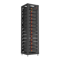
Battery Module Installation on Rack
1. Install the lug on the battery module and high-voltage control box.
2. Insert the rst battery module into the battery module rack at the bottom cluster rack; then in the order
from bottom to the top, continue the instalment in the same way till it reaches the twelfth oor. On the
thirteenth oor, insert the slide of the cabinet at the top of the rack into the high-voltage control box.
3. After the battery module and control box is inserted into the rack, use M4*12 outer hexagon cross com-
bination screws to x all the lugs of the battery module and control box on the side beam in turn.
4. After the battery module is placed in the control box, take out a 140 mm communication cable to con-
nect the communication port of the battery module and the high-voltage control box, and 11x110mm
communication cables to connect the battery module communication port (IN-OUT) from top to bottom.
(12 communication cables in total). The communication port (OUT) of the battery module at the
bottom is not connected to the communication cable. Instead, this port is sealed with a 120ohm
terminal resistor.
5. Take out a 220 mm positive power cord and connect the positive pole of the battery module at the top
to the positive pole of the high-voltage control box. Take out 11x200mm battery module power cords
and connect the power ports (B- to B+) in a top to bottom order to form a series circuit. For aesthetics,
connect the negative power pole of the rst battery module to the negative power pole of the high-volt-
age control box from the bottom of the battery module to the back of the rack. On the back of the rack,
a plane-head-shaped tie is used to secure the cable harness. (12 power cords in total).
6. Take out the external positive power cord EPCable5.0 and external negative power cord ENCable5.0, and
plug them into PCS interfaces, respectively.
7. Take out the ground wire A and connect one end of it to the M4 rivet nut of the high-voltage control box
panel, and the other end to any M6 screw hole of the cross beam above the rack. Take out the ground
wire B (user need to prepare in advance) and connect one end of it to any M6 screw hole of the cross
beam under the rack, and the other end to the customer's grounding point. (The length of the ground
wire B is determined based on the customer's condition.)
PLEASE NOTE
Before installing the battery, please turn the manual switch of the high-voltage control box to the o
position.
DANGER
Insucient or no grounding may cause an electric shock. Device malfunctions, and insucient or no
grounding may cause device damage and life-threatening electric shocks.
High Voltage Series Battery Startup Steps
After connecting the battery cables, press the air switch button on the high-voltage control box to turn OFF
to ON, and then press the START button. After the screen lights up, wait for about 8 seconds until the yellow
HV light indicator comes on. (The specic working time is subject to the HV light indicator's lighting-up time.)