High Voltage Series | Installer Manual16
Description of High-Voltage Control Box
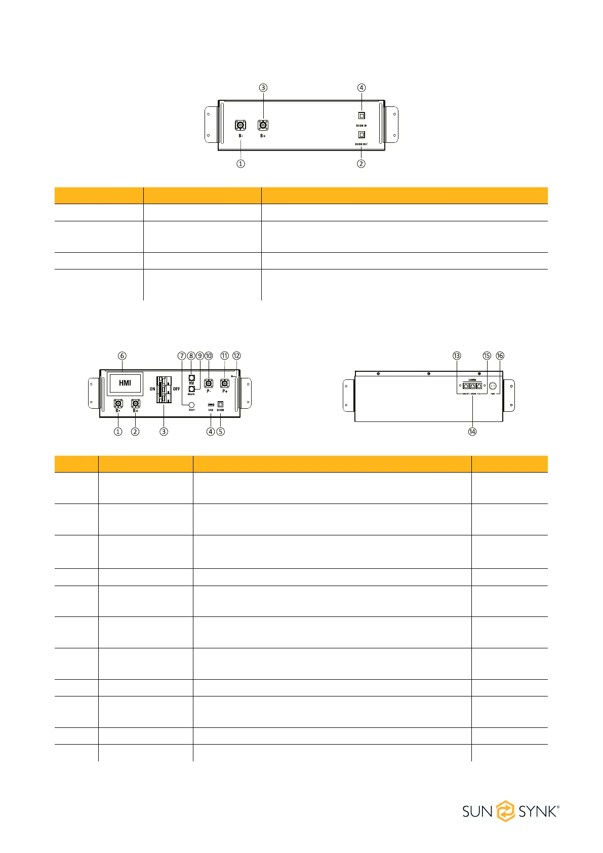
No. Name Description Position
1 B-
Connection position of the common negative pole of the
battery (black)
Front
2 B+
Connection position of the common positive pole of the
battery (orange)
Front
3 Air switch
Used to manually control the connection between the bat-
tery rack and external devices
Front
4 USB BMS upgrade interface and storage expansion interface Front
5 BCOM
Communicative connection with the rst battery module
and providing 12VDC power for the rst battery module
Front
6
Human-machine
interface (HMI)
Display some important battery information Front
7 START
A start switch of 12VDC power inside the high-voltage
control box
Front
8 HV light indicator High-voltage hazard indicator (yellow) Front
9
ALARM light indi-
cator
Battery system fault alarm indicator (red) Front
10 PCS - Connection position of PCS negative pole (black) Front
11 PCS+ Connection position of PCS positive pole (orange) Front
Description of Battery Module
No. Name Description
1 B- Battery module negative pole (black)
2 BCOM OUT
Connection position of battery module communication and
power supply output
3 B+ Battery module positive pole (orange)
4 BCOM IN
Connection position of battery module communication and
power supply input