High Voltage Series | Installer Manual18
Pin No. PCS Port Denition IN Port Denition OUT Port Denition Denition of Power
1 485B- BMS_CANL BMS_CANL 12V
2 485A+ BMS_CANH BMS_CANH GND
3 -- DI+ DO2+ --
4 PCANL DI- DO- --
5 PCANH -- -- --
6 -- -- -- --
7 485A+ -- -- --
8 485B- -- -- --
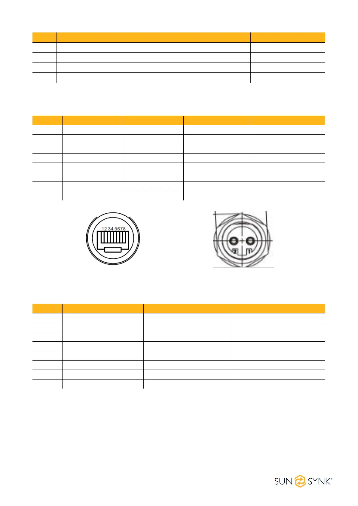
The following table presents the denition for PCS, IN, and OUT connection pins. All use the same pin num-
ber sequence shown in the next image:
Pin No. BMS-BMU Port Denition Upper BMU Port Denition Lower BMU Port Denition
1 BMU_CANL BMU_CANL BMU_CANL
2 BMU_CANH BMU_CANH BMU_CANH
3 DO+ DI+ DO+
4 DO- DI- DO-
5 GND GND GND
6 GND GND GND
7 12V 12V 12V
8 12V 12V 12V
The following table presents the denition of the high-voltage control box interface PCS, IN, and OUT con-
nection pins. All use the same pin number sequence shown in the next image:
No. Description Type
9 Connected to external PCS positive power cord (EPCable5.0) Optional
10 Connected to external PCS negative power cord (ENCable5.0) Optional
11 Connected to external 12V power cord (EPWRCable5.0) Optional
12 Connected to external device communication cable (ECOM Cable5.0) Optional