High Voltage Series | Installer Manual14
101
101
108
108
108
108
108
108
108
108
103
103
108
108
108
108
108
108
108
108
102
102
201x1
106
106
106
106
108
108
108
108
108
107
107
107
105
104
201
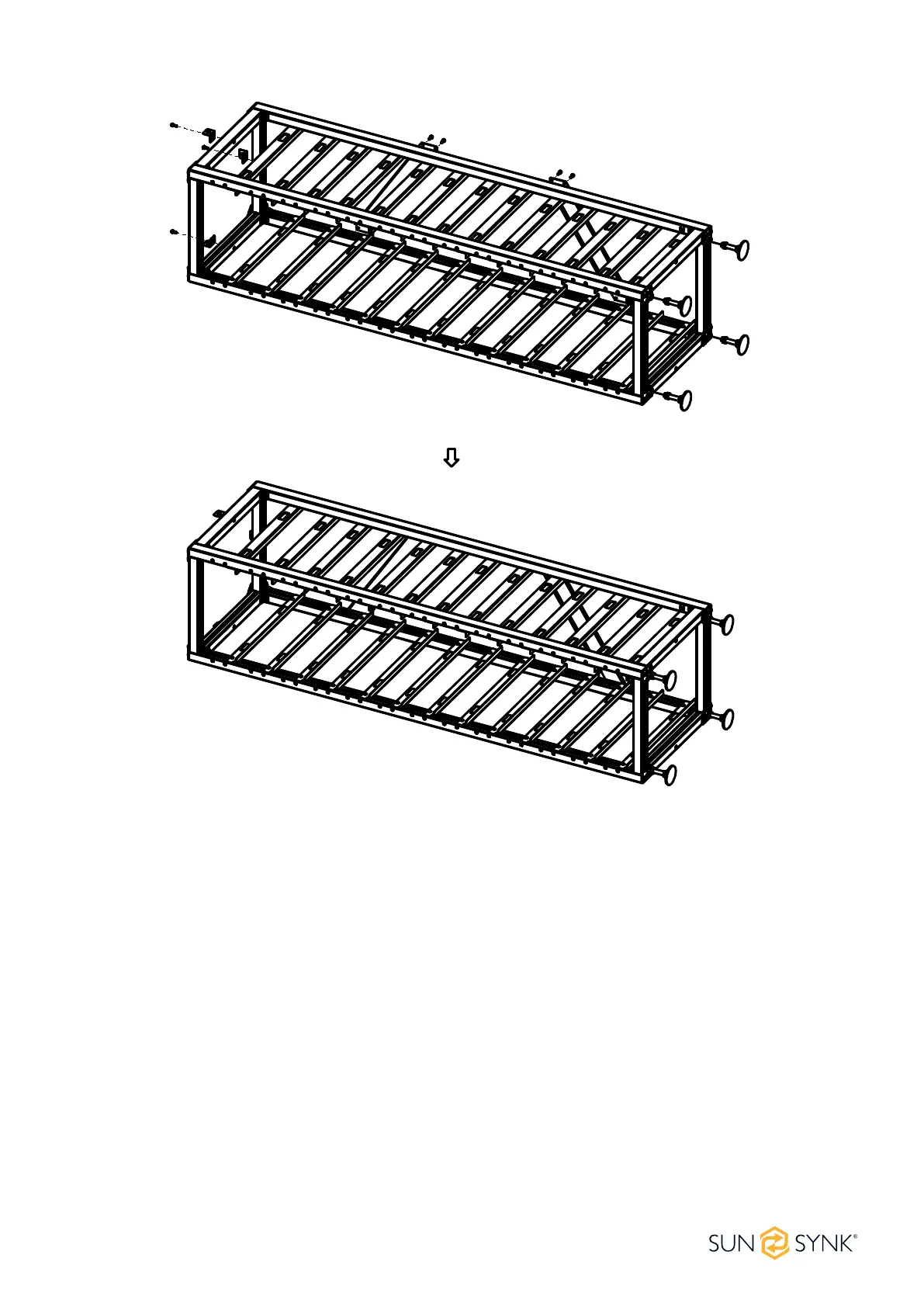
Type B:
1. Take out two side beams and upper and lower crossbeams to form a rectangular frame, connect with
side beams and crossbeams using big tripods and small tripods, and then x big and small triangular
supports with side beams and crossbeams using M6*12 outer hexagon cross combination screws and a
PHILIP2 # screwdriver.
2. Use a PHILIP2 # screwdriver and M6*12 outer hexagon cross combination screws to x the L-bracket
assembly horizontally on the side beam.
3. Fix the diagonal brace on two side beams using M6*12 outer hexagon cross combination screws and a
screwdriver.
4. Fix the four bottom plates on four corners of the lower rack using the M6*12 outer hexagon cross com-
bination screws and a PHILIP2# screwdriver.
5. Screw the base into the bottom plate and x it with a PHILIP2# screwdriver or by hand.
6. To x the rack on the wall, use a PHILIP2# screwdriver to install the rack fastener at the M6 screw hole
above the rack and x it with M6*12 outer hexagon cross combination screws. Fix the other side of the
rack with the wall using M6*100 expansion screws. To x two racks together, install the rack fastener at
the M6 screw hole above the rack, and x them together with M6*12 outer hexagon cross combination
screws and M6 nuts.