12
NOTE: DIAGRAMS & ILLUSTRATIONS ARE NOT TO SCALE.
INNOVATIVE HEARTH PRODUCTS • DIRECT-VENT GAS FIREPLACES (DRT6300/DRC6300) • INSTALLATION INSTRUCTIONS
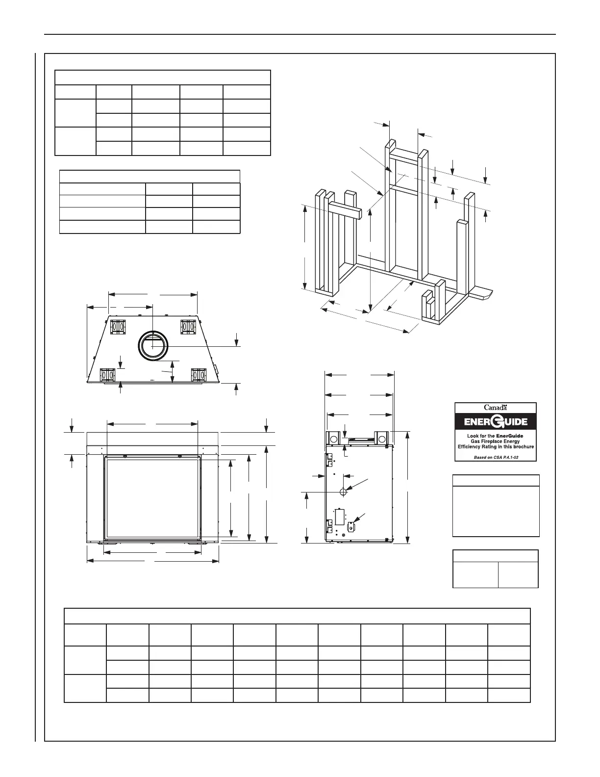
Figure 11—Fireplace and Framing Specifications
E
A
B
D
Top View
Front View
5-3/32 (129)
Right Side View
14-1/8
8-1/2”
(216)
5-1/4”
(133)
(359)
26-15/32
(672)
C
25-29/32
(658)
25-1/2
(648)
7
1/2 (13)
(178)
19-5/8
(498)
Gas Inlet
(This
Side
Only)
Electrical
Inlet
10-3/8
(264)
F
G
H
J
Fireplace Dimensions
Model
A B C D E F G H J
40 in.
in. 50-5/8 39-1/4 45 25-5/16 34 37-5/8 33-3/32 29-9/32 34-3/4
mm 1286 997 1143 643 864 956 840 744 883
45 in.
in. 56-11/16 44-1/4 50 28-3/8 40-1/8 43-5/8 38-3/32 34-1/2 40-59/64
mm 1440 1124 1270 721 1019 1108 968 876 1039
Notes
Diagrams, illustrations and photo-
graphs are not to scale — consult
installation instructions. Product
designs, materials, dimensions,
specifications, colors and prices are
subject to change or discontinuance
without notice.
Vent Size
Coaxial DV
Vent Size
8" Inner
11" Outer
Framing Dimensions
Model A B C
40 in.
in. 50-3/4 45 75-1/8
mm 1289 1143 1908
45 in.
in. 56-7/8 50 80-1/16
mm 1445 1270 2034
A
B
C
8-1/2
(216)
13
(
330
)
VENT FRAMING
TOP VENT WITH 2 FEET
VERTICAL VENT AND
ONE 90° ELBOW
Framing should be constructed
of 2x4 or larger lumber.
Inches (mm)
(641)
25-1/4
15
(
381
)
6-1/2
(165)
1/2 A
PIPE CENTERLINE
A
B
C
8-1/2
(216)
13
(
330
)
VENT FRAMING
TOP VENT WITH 2 FEET
VERTICAL VENT AND
ONE 90° ELBOW
Framing should be constructed
of 2x4 or larger lumber.
Inches (mm)
(641)
25-1/4
15
(
381
)
6-1/2
(165)
1/2 A
PIPE CENTERLINE
Thermal Efficiency (%)
Natural Gas Propane
Model P4 P4
40 in. 35.8 42.0
45 in. 47.2 47.0