18
NOTE: DIAGRAMS & ILLUSTRATIONS ARE NOT TO SCALE.
INNOVATIVE HEARTH PRODUCTS • DIRECT-VENT GAS FIREPLACES (DRT6300/DRC6300) • INSTALLATION INSTRUCTIONS
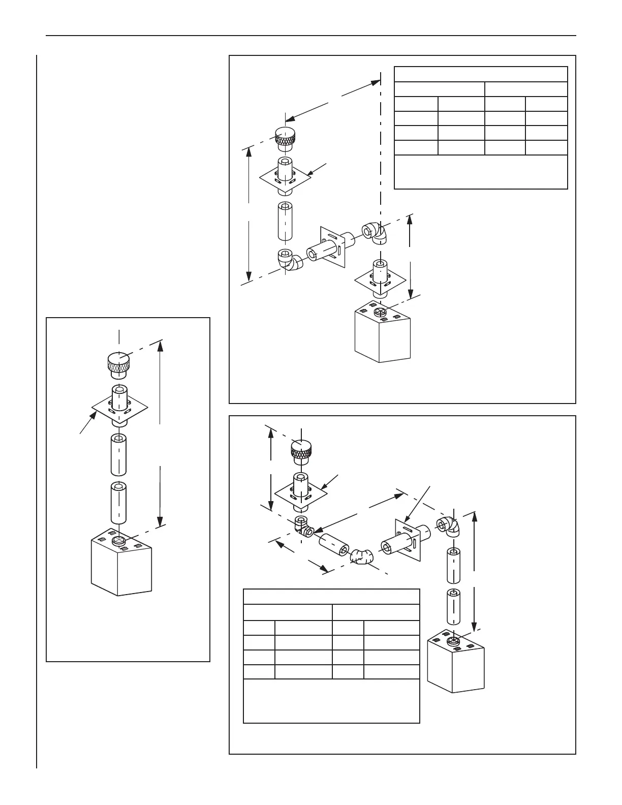
Figure 25—Top Vent—Three Elbows
V
H
1
H
V
1
Ceiling
Firestop/Spacer
(SV8BF)
Wall
Firestop/Spacer
(SV8HF)
Table B
H + H
1
Maximum
V Minimum
feet (meter) feet (meter)
10 (3.1) 2.5 (0.762)
15 (4.65) 3.5 (1.06)
20 (6.2) 4.5 (1.37)
H + H
1
= 20 feet (6.2 m) Max.
V + V
1
+ H + H
1
= 40 ft. (12.4 m) Max.
V + V
1
= 11 feet (3.3 meters) Min. for 40 in. units
V + V
1
= 10.5 feet (3.2 meters) Min. for 45 in. units
Figure 24—Top Vent—Two 90 Degree Elbows (Corner Framing with Square
Termination (SV8HTS))
H
V
V1
Ceiling
Firestop/Spacer
(SV8BF)
Table A
H Maximum
V Minimum
feet (meter) feet (meter)
10 (3.1) 2.5 (0.762)
15 (4.65) 3.5 (1.07)
20 (6.2) 4.5 (1.37)
V + V
1
+ H = 40 feet (12.4 meters) Max.
V + V
1
= 11 feet (3.3 meters) Minimum for 40 in. units
V + V
1
= 10.5 feet (3.2 meters) Minimum for 45 in. units
40 feet (12.2 meters)
Maximum
6 feet (1.8 meters)
Minimum
Ceiling
Firestop/Spacer
(SV8BF)
Figure 23—Top Vent—Straight
VERTICAL VENT FIGURES/TABLES
NOTES:
• Secure Vent
®
(rigid vent pipe) is shown in
the figures.
• It is very important that the horizontal/
inclined run be maintained in a straight
(no dips), slightly elevated plane. The
recommended incline is approximately
1/4" per foot (20 mm per meter) horizontal,
in a direction away from the fireplace. The
rise per foot run ratios that are smaller are
acceptable all the way down to at or near
level.
• SV8BF (Secure Vent) firestop/spacer must
be used anytime vent pipe passes through a
combustible floor or ceiling. SV8HF (Secure
Vent) firestop/spacer must be used anytime
vent pipe passes through a combustible wall.
• Two 45º elbows may be used in place of one
90º elbow. The same rise to run ratios, as
shown in the venting figures for 90º elbows,
must be followed if 45º elbows are used.
A Vent Restrictor, as shown in Figure 17 on Page
12, may need to be used in this application
Example: If 20 feet of (H) horizontal
vent run is needed, then 4-1/2 feet
minimum of (V) vertical vent will be
required.
A Vent Restrictor, as shown in
Figure 14 on Page 14, must be used
in this application.
Example: If 20 feet of (H+ H
1
) horizon-
tal vent run is needed, then 4-1/2 feet
minimum of (V) vertical vent will be
required.
A Vent Restrictor, as
shown in
Figure 14 on Page 14,
must be used in this
application.