46
NOTE: DIAGRAMS & ILLUSTRATIONS ARE NOT TO SCALE.
Pilot Tube
Spark
Sensor
IPI Pilot
885 Valve
Optional
Split Flow
BL
W
Y
Y
BR
G
O
O
R
R
B
B
G
GY
R
B
BL
WH
B
B
W
G
Battery Holder w/Switch
ON/ Remote
/OFF
Battery Holder
Wire Harness
Reset Switch
(See instructions.)
Power Vent Blower
Power Vent
Models Only
Air Pressure Switch
Power Vent Only
Note: On models
without pressure
switch, these
connectors are
plugged together.
Main Wire
Harness
Control Module
G
B
G
W
B
Fuse
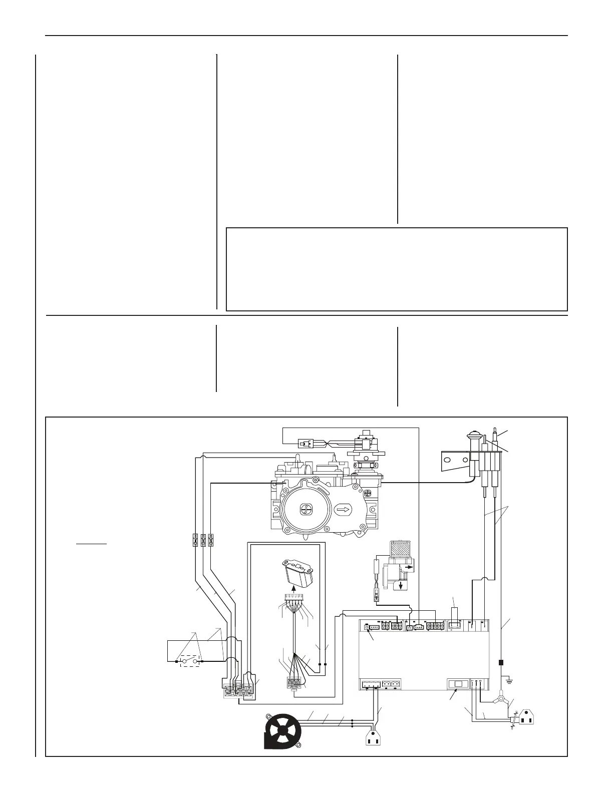
ELECTRONIC WIRING DIAGRAM
Ground Y
B
Battery
Holder
with Switch
ON/Remote/OFF
(Schematic representation only)
COLOR CODE:
B = Black
BB = Brown w/Black Stripe
BG = Brown w/Green Stripe
BL = Blue
BR = Brown
G = Green
GY = Gray
O = Orange
R = Red
W = White
Y = Yellow
CAUTION: LABEL ALL WIRES PRIOR
TO DISCONNECTION WHEN SERVICING
CONTROLS. WIRING ERRORS CAN
CAUSE IMPROPER AND DANGEROUS
APPLIANCE OPERATION.
ATTENTION : AU MOMENT DE
L'ENTRETIEN DES COMMANDES,
ÉTIQUETEZ TOUS LES FILS AVANT DE
LES DÉBRANCHER. DES ERREURS DE
CÁBLAGE PEU-VENT ENTRAÎNER UN
FONCTIONNEMENT INADÉQUAT ET
DANGEREUX.
ORDERING REPLACEMENT PARTS
A complete parts list is found at the end of
this manual. Use only parts supplied from the
manufacturer.
With proper care and maintenance, your appli-
ance will provide many years of enjoyment. If
you should experience any problem, first refer
to the troubleshooting guide in this manual.
If problem persists, contact your Innovative
Hearth Products dealer or distributor.
Normally, all parts should be ordered through your
Innovative Hearth Products distributor or dealer.
Parts will be shipped at prevailing prices at
time of order.
Fireplace Model Number ________________________________________________
Fireplace Serial Number _________________________________________________
Date Installed _________________________________________________________
Type of Gas Used in Fireplace ____________________________________________
Dealer Name _________________________________________________________
When ordering repair parts always provide:
1. The model number of the appliance.
2. The serial number of the appliance.
3. The part number.
4. The description of the part.
5. The quantity required.
6. The installation date of the appliance.
If you encounter any problems or have any
questions concerning the installation or ap-
plication of this system, please contact your
dealer or distributor.
PRODUCT REFERENCE INFORMATION
We recommend that you record the important
reference information about your fireplace in
the space provided below.
Please call Innovative Hearth Products for the
phone number of your nearest Innovative Hearth
Products dealer who will answer your questions
or address your concerns.
INNOVATIVE HEARTH PRODUCTS
1508 Elm Hill Pike, Suite 108
Nashville, TN 37210
Visit us at
SuperiorFireplaces.US.com
Figure 75—Wiring Diagram
WIRING
Wiring diagrams are provided here for refer-
ence purposes only. This information is also
provided on schematics attached directly to
the appliance on a pullout panel located within
the control compartment.
SCHEMATIC REPRESENTATION ONLY
INNOVATIVE HEARTH PRODUCTS • DIRECT-VENT GAS FIREPLACES (DRT6300/DRC6300) • CARE AND OPERATION INSTRUCTIONS