34
NOTE: DIAGRAMS & ILLUSTRATIONS ARE NOT TO SCALE.
INNOVATIVE HEARTH PRODUCTS • DIRECT-VENT GAS FIREPLACES (DRT6300/DRC6300) • INSTALLATION INSTRUCTIONS
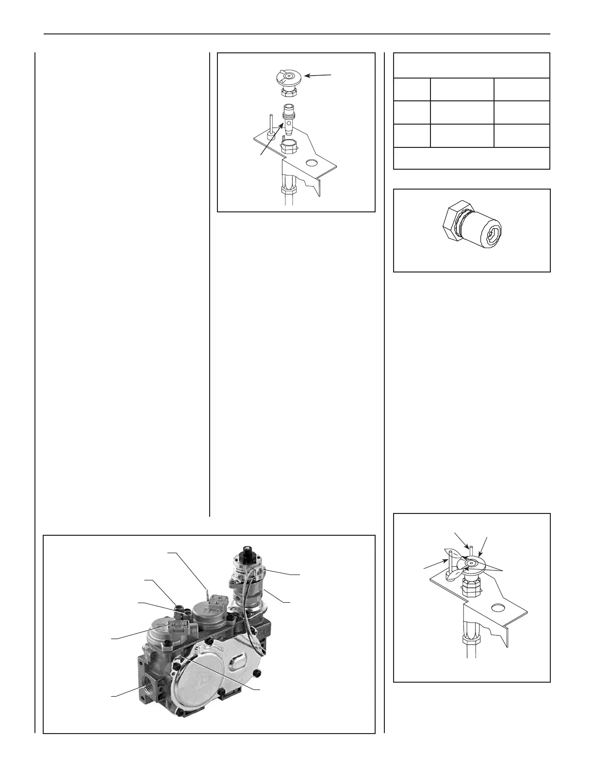
Pilot Hood
Igniter Rod
Flame
Sensor
Pilot
Nozzles
Pilot
Orifice
Pilot
Hood
Wire
(from DFC Wire
Harness)
Pressure Regulator
Tower
Main Gas Inlet
3/8" NPT
Green Wire
(from DFC Wire Harness)
Inlet (IN) Test Port
Manifold (OUT) Test Port
Connect GTMS
wire harness.
Yellow Ground Wire
(from DFC Wire Harness)
Step 16. Relight the main burner and verify
proper burner ignition and operation. See Burner
Adjustments Pages 26 and 27.
Inspect the pilot system for proper flame. The
pilot flame should engulf the flame sensor as
shown in Figure 59.
The lighting instructions can be found on the
lighting label in the control compartment or in
the Care and Operation Manual provided with
the appliance.
Step 17. Using a manometer, test the inlet and
manifold gas pressures. See Tables 2 and 3
on Page 6.
ALWAYS TEST PRESSURES WITH THE VALVE
REGULATOR CONTROL AT THE HIGHEST
SETTING.
SEE PAGE 28 FOR AIR SHUTTER ADJUSTMENT
GUIDELINES.
A. Remove the orifice from the manifold and
replace it with the one provided in the kit. See
the following table for orifice sizes for natural
and propane models. Figure 58 illustrates
the orifice. Use pipe joint compound or Tef-
lon tape on all pipe fittings before installing
(ensure propane resistant compounds are
used in propane applications, do not use pipe
joint compounds on flare fittings).
B. Retrieve the burner and slide the venturi tube
over the orifice. Set the burner assembly into
its position and secure it.
C. Reinstall the grate assembly.
Step 13. Reassemble the remaining compo-
nents by reversing the procedures outlined in
the preceding steps.
Step 14. Attach the conversion label provided
in the conversion kit to the rating plate on the
appliance.
Step 15. Apply gas to the system and relight
appliance. With the main burner "ON", test the
new pressure regulator assembly and all gas
line joints for leaks using a gas leak test solu-
tion. See Test All Connections For Gas Leaks
on Page 25.
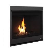
Figure 58
Step 6. Refer to the instructions provided
with the SIT regulator conversion kit. Using a
Torx T20 (with 1/4" shank and center hole) or
slotted screwdriver, remove and discard the
two pressure regulator mounting screws, the
pressure regulator tower, and the diaphragm
assembly (if applicable). Properly dispose of
all removed components. Make sure the rubber
gasket installed on the back of the replacement
pressure regulator is properly positioned.
Step 7. Install the new stepper motor pressure
regulator assembly using the supplied screws.
Securely tighten the screws (25 in-lbs).
Step 8. Attach the enclosed identification label
to the valve body where it can be easily seen.
Step 9. Make stepper motor and valve
electrical connections.
Step 10. Remove the pilot hood assembly to
access the hexed pilot orifice. Using a 5/32". al-
len wrench, remove and replace the pilot orifice
with the one provided with the kit.
NOTE: Use extreme care to avoid
damaging the igniter assembly.
Step 11. Refer to Figure 57 and remove the
pilot hood assembly to access the hexed pilot
orifice. Remove and replace the orifice with the
one provided with the kit.
Step 12. (Refer to Figure 55 on Page 33 and
Figure 58)
VERIFY THE PROPER ORIFICE SIZE BE-
FORE INSTALLING IT.
Figure 56
Burner Orifice Sizes
Elevation 0-4500 feet ( 0-1372 meters)
Model
Natural Gas
drill size (inches)
Propane
drill size (inches)
40 in.
0.1405" (#28)*
• H2286
0.086" (#44)*
• H2287
45 in.
0.150" (#25)*
• XXXXX
0.086" (#44)*
• H2287
Table 11
* Standard size installed at factory
• Part /Cat. Number
Figure 59
Figure 57