8
NOTE: DIAGRAMS & ILLUSTRATIONS ARE NOT TO SCALE.
INNOVATIVE HEARTH PRODUCTS • DIRECT-VENT GAS FIREPLACES (DRT6300/DRC6300) • INSTALLATION INSTRUCTIONS
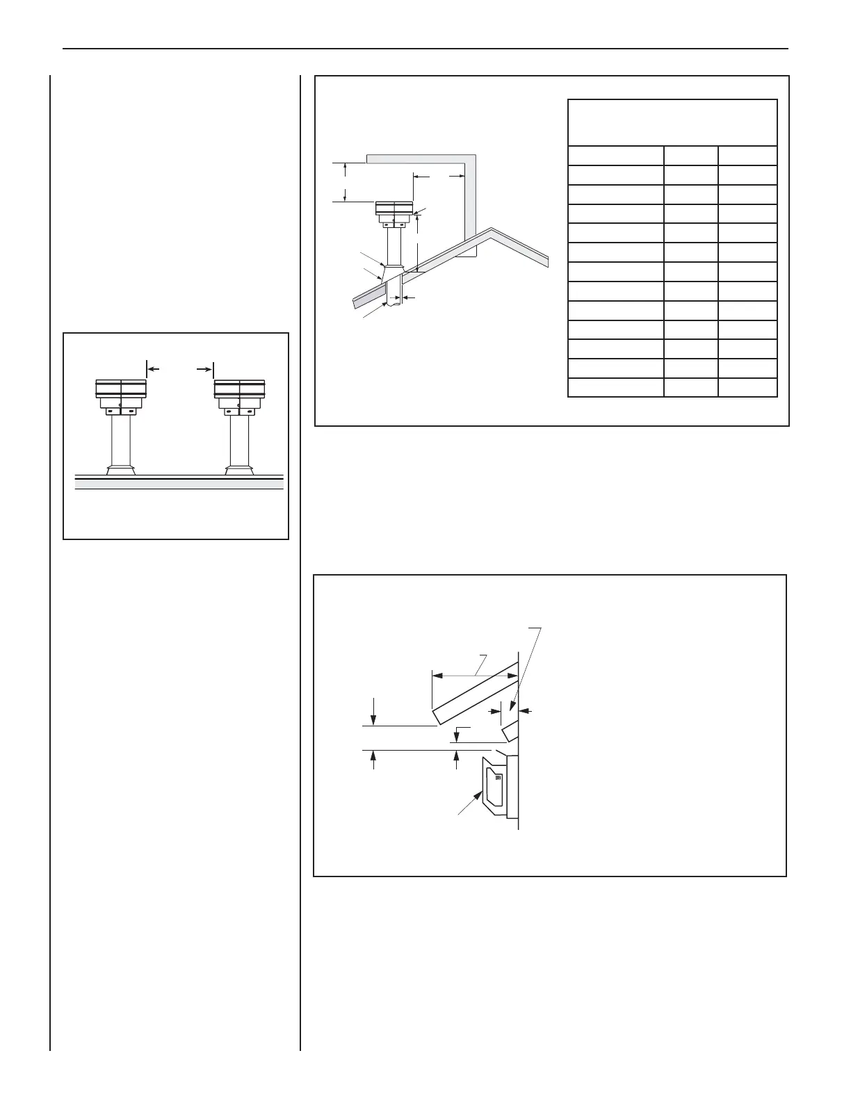
3"
(76 mm)
Termination Kit
Combustible Projection
greater than 2-1/2” in length
Horizontal Vent Termination Clearances
Combustible Projection
2-1/2” or less in length
24"
(610 mm)
Ventilated Or
Unventilated Soffit
See Figure 28 on Page 20 for the recess allowances, into
exterior walls, of the square horizontal terminations.
Termination Heights For Vents
Above Flat Or Sloped Roofs
Ref. NFPA 54 / ANSI Z223.1
Roof Pitch * Feet * Meters
Flat to 6/12 1.0 0.3
6/12 to 7/12 1.25 0.38
7/12 to 8/12 1.5 0.46
8/12 to 9/12 2.0 0.61
9/12 to 10/12 2.5 0.76
10/12 to 11/12 3.25 0.99
11/12 to 12/12 4.0 1.22
12/12 to 14/12 5.0 1.52
14/12 to 16/12 6.0 1.83
16/12 to 18/12 7.0 2.13
18/12 to 20/12 7.5 2.29
20/12 to 21/12 8.0 2.44
The vent / air intake termination clearances
above the high side of an angled roof is as
shown in the following chart:
12
X
Roof Pitch is X/12
2 FT
MIN.
2 FT MIN.
Lowest
Discharge
Opening
H*
*H = MINIMUM HEIGHT FROM ROOF TO
LOWEST DISCHARGE OPENING OF VENT
TERMINATION HEIGHTS FOR VENTS ABOVE
FLAT OR SLOPED ROOFS
Horizontal Overhang
Vertical
Wall
Vent
Termination
Storm Collar
Concentric
Vent Pipe
Flashing
1” (25.4 mm) Minimum
Clearance to Combustibles
Vertical Vent Termination Clearances
Figure 4
VENT TERMINATION CLEARANCES
These instructions should be used as a
guideline and do not supersede local codes
in any way. Install vent according to local
codes, these instructions, the current National
Fuel Gas Code (ANSI-Z223.1) in the USA or
the current standards of CAN/CGA-B149.1 in
Canada.
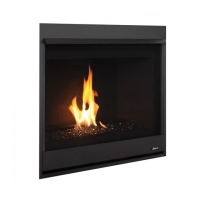
Vertical Vent Termination Clearances
Terminate multiple vent terminations according
to the installation codes listed above. Also see
Figure 3.
Terminate single vent caps relative to building
components according to Figures 3 and 4.
Horizontal Vent Termination Clearances
The horizontal vent termination must have a minimum of 3" (76 mm) clearance to any overhead
combustible projection of 2-1/2" (64 mm) or less (see Figure 5). For projections exceeding 2-1/2"
(64 mm), see Figure 5. For additional vent location restrictions refer to Figure 6 on Page 9.
12”
(305mm)
Minimum
Figure 3—Multiple Terminations
Figure 5—Side Elevation View