5-10
SUPERSERVER 5018D-FN4T User's Manual
Control Panel Connectors
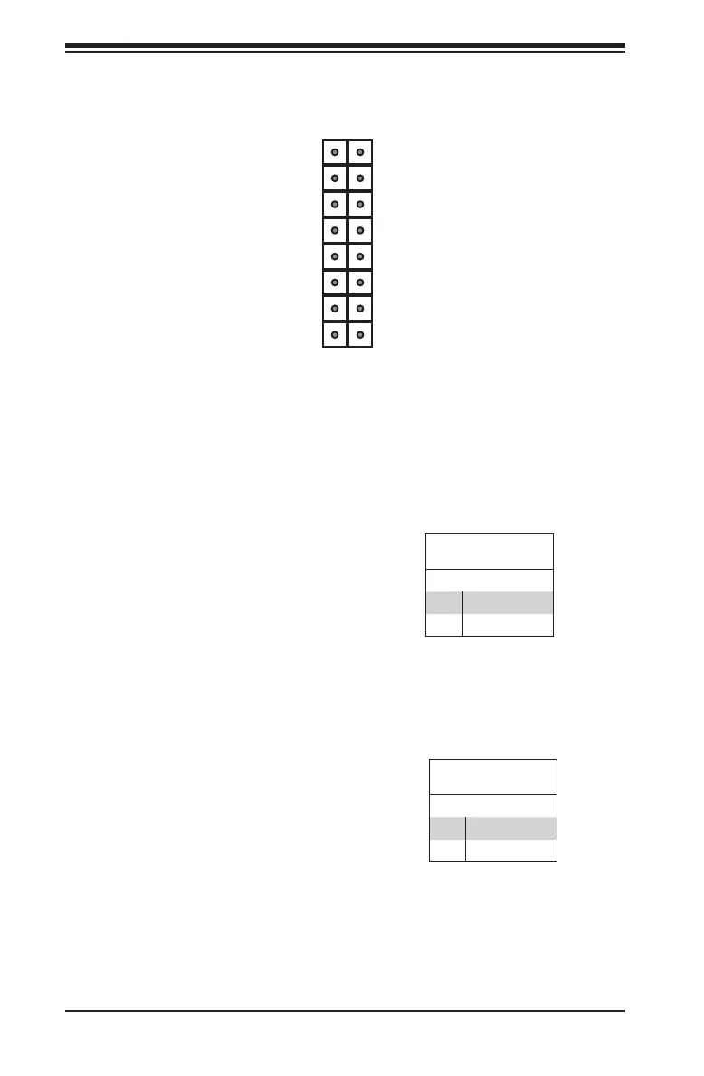
Figure 5-4. Control Panel Header Pins
3.3 V
3.3 V stby
3.3 V stby
3.3 V stby
UID LED
3.3 V
Reset (Button)
Power (Button)
Power On LED
HDD LED
NIC1 LED (Activity)
NIC2 LED (Activity)
OH/Fan Fail/Pwr Fail
X
Ground
Ground
2 1
16 15
Power Button
The Power Button connection is
located on pins1 and 2 of JF1.
Momentarily contacting both pins will
power on/off the system. This button
can also be congured to function as
a suspend button (with a setting in the
BIOS--see Chapter 7). To turn off the
power in the suspend mode, press
the button for at least 4 seconds.
Refer to the table on the right for pin
denitions.
Power Button
Pin Denitions (JF1)
Pin# Denition
1 Signal
2 Ground
Reset Button
The reset button is located on pins
3 and 4 of JF1 and attaches to the
reset switch on the computer chassis.
See the table on the right for pin
denitions.
Reset Button
Pin Denitions (JF1)
Pin# Denition
3 Reset
4 Ground

 Loading...


