50
Chapter 3: Maintenance and Component Installation
3.7 Storage Drives
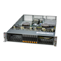
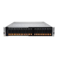
The CSE-217BD2 chassis supports 24 hot-swap 2.5" hybrid storage drive bays. Each node
controls 12 drives. For each node, two drives support NVMe PCIe 5.0 and the remaining
drives support NVMe PCIe 4.0.
• DNTR: 24 hybrid NVMe/SATA3 drive bays
• DNC8R: 24 hybrid SAS3/NVMe drive bays (SAS3 supported via Broadcom 3816 AOC)
Drive Carriers
Each drive carrier has two LED indicators: an activity indicator and a status indicator. For
RAID congurations using a controller, the meaning of the status indicator is described in
the table below. For OS RAID or non-RAID congurations, some LED indications are not
supported, such as hot spare.
Drive Carrier LED Indicator
Color Blinking Pattern Behavior for Device
Activity LED
Blue Solid On SAS/NVMe drive installed
Blue Blinking I/O activity
Status LED
Red Solid On Failure of drive with RSTe support
Red Blinking at 1 Hz Rebuild drive with RSTe support
Red
Blinking with two blinks and one
stop at 1 Hz
Hot spare for drive with RSTe support
(not supported in VMD mode)
Red On for ve seconds, then o Power on for drive with RSTe support
Red Blinking at 4 Hz Identify drive with RSTe support
Green Solid On
Safe to remove NVMe device (not
supported in VMD mode)
Amber Blinking at 1 Hz
Attention state---do not remove NVMe
device (not supported in VMD mode)
Note: Enterprise level hard disk drives are recommended for use in Supermicro chassis and
servers. For information on recommended HDDs, see the Supermicro website, http://www.
supermicro.com/products/nfo/les/storage/SBB-HDDCompList.pdf.
 Loading...
