25
Chapter 2: Installation
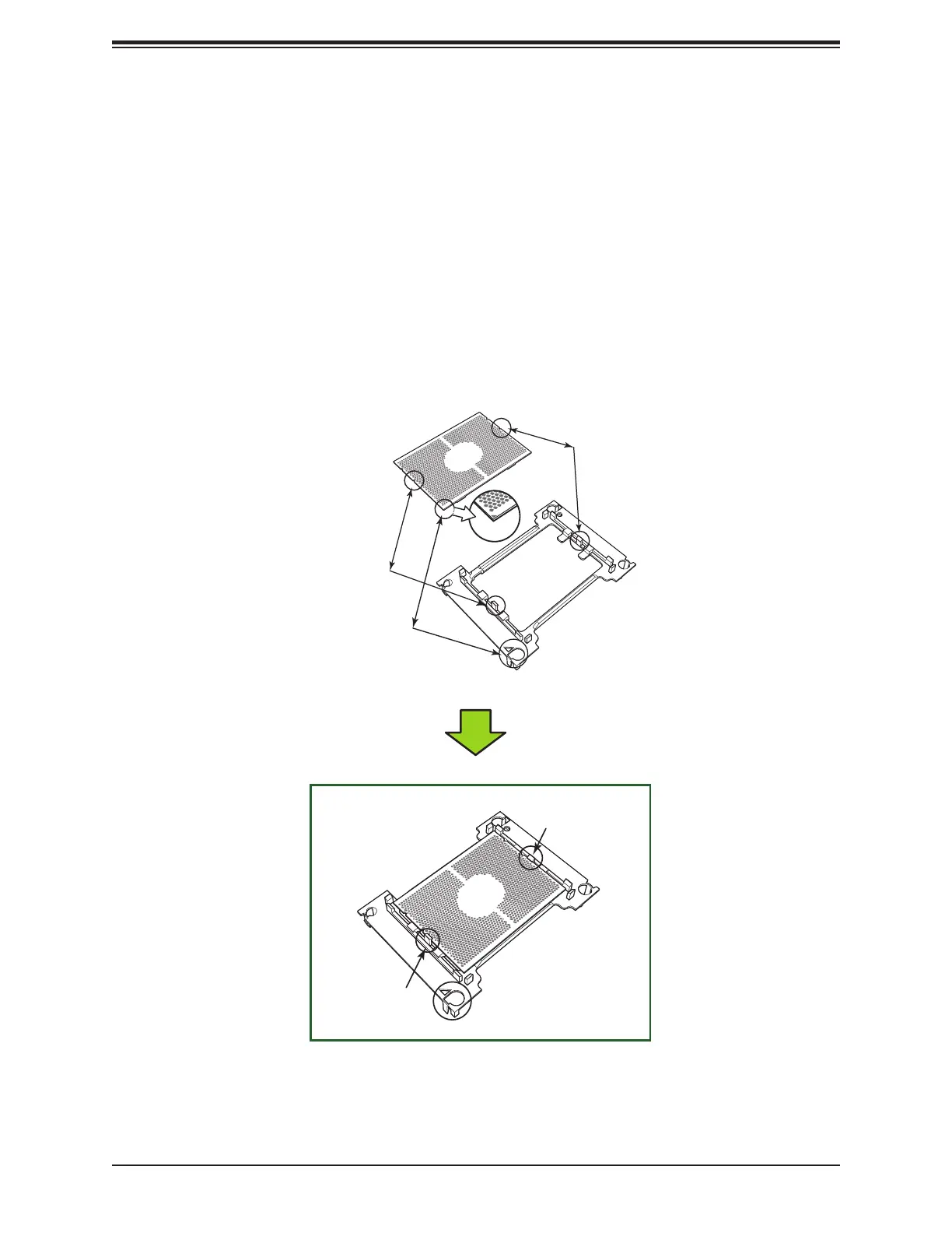
Creating the Non-F Model Processor Carrier Assembly
To install a Non-F model processor into the processor carrier, follow the steps below:
1. Hold the processor with the LGA lands (gold contacts) facing up. Locate the small, gold
triangle in the corner of the processor and the corresponding hollowed triangle on the
processor carrier. These triangles indicate pin 1. See the images below.
2. Using the triangles as a guide, carefully align and place Point A of the processor into
Point A of the carrier. Then gently ex the other side of the carrier for the processor to t
into Point B.
3. Examine all corners to ensure that the processor is rmly attached to the carrier.
Processor Carrier Assembly (Non-F Model)
A
A
B
B
Pin 1
Align CPU Pin 1
CPU (Upside Down)
with CPU LGA Lands up
Processor Carrier
(Upside Down)
Align Point B of the CPU and
Point B of the Processor Carrier
Align Point A of the CPU and
Point A of the Processor Carrier
Pin 1
A
B
Allow carrier to
latch onto CPU
Allow carrier to
latch onto CPU

 Loading...


