60
Super X11SPi-TF User's Manual
SAN MAC
DESIGNED IN USA
BIOS
LICENSE
X11SPi-TF
REV:1.02
IPMI CODE
MAC CODE
BAR CODE
JTPM1
JPWR1
MH11
MH10
JRK1
BT1
SP1
+
LEDBMC
LE3
LEDPWR
C
JL1
JOH1
JBT1
JSTBY1
JSD1
JSD2
JWD1
JPG1
JPME2
JIPMB1
JNVI2C1
FAN4
FAN3 FAN2
FAN1
FANA
FANB
FAN5
JPI2C1
JD1
I-SGPIO2
S-SGPIO1
I-SGPIO1
I-SATA4
I-SATA5
I-SATA6
I-SATA7
I-SATA0
S-SATA0
S-SATA1
I-SATA1
I-SATA2
I-SATA3
JF1
JPWR2
M.2 PCI-E 3.0 X4
USB10(3.0)
USB8/9(3.0)
USB6/7(3.0)
USB4/5
USB2/3
COM1
COM2
USB0/1
IPMI_LAN
LAN1
LAN2
VGA
UID-SW
UID-LED
PCH SLOT1 PCI-E 3.0 X4(IN X8)
CPU SLOT2 PCI-E 3.0 X8
CPU SLOT3 PCI-E 3.0 X8
CPU SLOT4 PCI-E 3.0 X16
CPU SLOT6 PCI-E 3.0 X16
CPU
DIMMF1
DIMME1
DIMMD1
DIMMD2
DIMMA2
DIMMA1
DIMMB1
RST
JF1
ON
PWR UID
LED
PS
FAIL 1
NIC
2
NIC
NMIX
PWRHDD
LEDLED
Intel
C622
ASpeed
AST2500
JPTG1
Intel
X557
DIMMC1
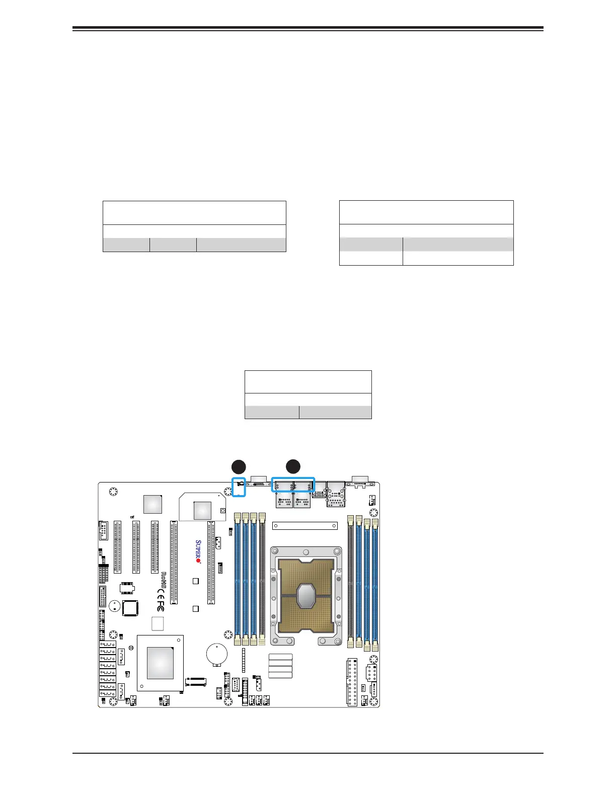
2.9 LED Indicators
LAN LEDs
Two LAN ports (LAN 1 and LAN 2) are located on the I/O back panel of the motherboard.
Each Ethernet LAN port has two LEDs. The green LED indicates activity, while the other Link
LED may be green, amber, or o to indicate the speed of the connection. Refer to the tables
below for more information.
LAN1/2 Activity LED (Right)
LED State
Color Status Denition
Green Flashing Active
1
LAN1/2 Link LED (Left)
LED State
LED Color Denition
Green 10Gbps
Yellow/Amber 1Gbps
UID LED
LED Indicator
LED Color Denition
Blue: On Unit Identied
Unit ID LED
A rear UID LED indicator (UID-LED) is located near the UID switch on the I/O back panel.
This UID indicator provides easy identication of a system unit that may need service.
2
1. LAN 1/2 LED
2. UID LED

 Loading...


