35
Chapter 2: Installation
SAN MAC
DESIGNED IN USA
BIOS
LICENSE
X11SPi-TF
REV:1.02
IPMI CODE
MAC CODE
BAR CODE
JTPM1
JPWR1
MH11
MH10
JRK1
BT1
SP1
+
LEDBMC
LE3
LEDPWR
C
JL1
JOH1
JBT1
JSTBY1
JSD1
JSD2
JWD1
JPG1
JPME2
JIPMB1
JNVI2C1
FAN4
FAN3 FAN2
FAN1
FANA
FANB
FAN5
JPI2C1
JD1
I-SGPIO2
S-SGPIO1
I-SGPIO1
I-SATA4
I-SATA5
I-SATA6
I-SATA7
I-SATA0
S-SATA0
S-SATA1
I-SATA1
I-SATA2
I-SATA3
JF1
JPWR2
M.2 PCI-E 3.0 X4
USB10(3.0)
USB8/9(3.0)
USB6/7(3.0)
USB4/5
USB2/3
COM1
COM2
USB0/1
IPMI_LAN
LAN1
LAN2
VGA
UID-SW
UID-LED
PCH SLOT1 PCI-E 3.0 X4(IN X8)
CPU SLOT2 PCI-E 3.0 X8
CPU SLOT3 PCI-E 3.0 X8
CPU SLOT4 PCI-E 3.0 X16
CPU SLOT6 PCI-E 3.0 X16
CPU
DIMMF1
DIMME1
DIMMD1
DIMMD2
DIMMA2
DIMMA1
DIMMB1
RST
JF1
ON
PWR UID
LED
PS
FAIL 1
NIC
2
NIC
NMIX
PWRHDD
LEDLED
Intel
C622
ASpeed
AST2500
JPTG1
Intel
X557
DIMMC1
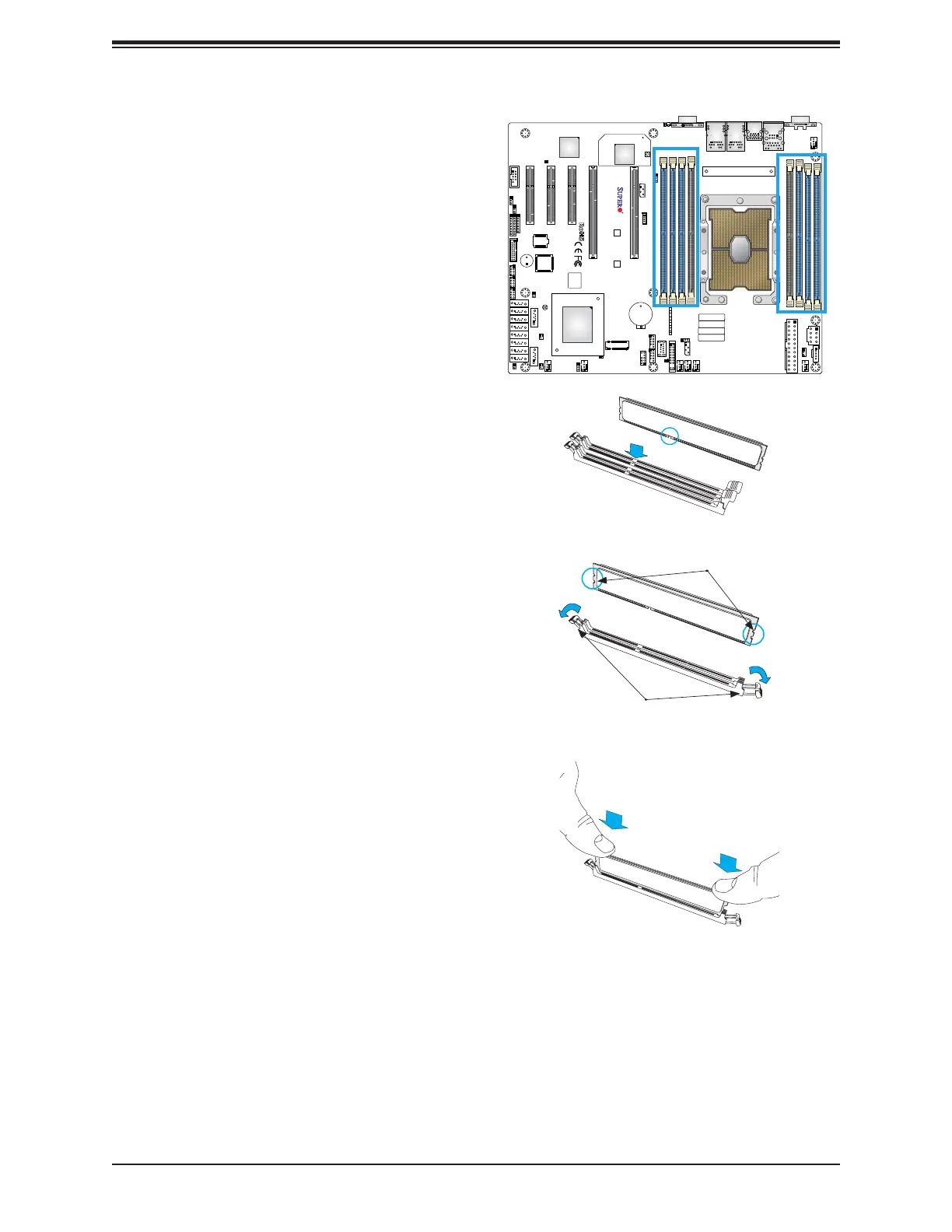
DIMM Installation
1. Insert the desired number of DIMMs
into the memory slots based on the
recommended DIMM population table on
pg. 32.
2. Push the release tabs outwards on both
ends of the DIMM slot to unlock it.
3. Align the key of the DIMM module with the
receptive point on the memory slot.
4. Align the notches on both ends of the
module against the receptive points on the
ends of the slot.
5. Press the notches on both ends of the
module straight down into the slot until the
module snaps into place.
6. Press the release tabs to the lock positions
to secure the DIMM module into the slot.
DIMM Removal
Press both release tabs on the ends of the
DIMM module to unlock it. Once the DIMM
module is loosened, remove it from the
memory slot.
Release Tabs
Notches
Press both notches
straight down into
the memory slot.

 Loading...


