46
Super X11SPi-TF User's Manual
SAN MAC
DESIGNED IN USA
BIOS
LICENSE
X11SPi-TF
REV:1.02
IPMI CODE
MAC CODE
BAR CODE
JTPM1
JPWR1
MH11
MH10
JRK1
BT1
SP1
+
LEDBMC
LE3
LEDPWR
C
JL1
JOH1
JBT1
JSTBY1
JSD1
JSD2
JWD1
JPG1
JPME2
JIPMB1
JNVI2C1
FAN4
FAN3 FAN2
FAN1
FANA
FANB
FAN5
JPI2C1
JD1
I-SGPIO2
S-SGPIO1
I-SGPIO1
I-SATA4
I-SATA5
I-SATA6
I-SATA7
I-SATA0
S-SATA0
S-SATA1
I-SATA1
I-SATA2
I-SATA3
JF1
JPWR2
M.2 PCI-E 3.0 X4
USB10(3.0)
USB8/9(3.0)
USB6/7(3.0)
USB4/5
USB2/3
COM1
COM2
USB0/1
IPMI_LAN
LAN1
LAN2
VGA
UID-SW
UID-LED
PCH SLOT1 PCI-E 3.0 X4(IN X8)
CPU SLOT2 PCI-E 3.0 X8
CPU SLOT3 PCI-E 3.0 X8
CPU SLOT4 PCI-E 3.0 X16
CPU SLOT6 PCI-E 3.0 X16
CPU
DIMMF1
DIMME1
DIMMD1
DIMMD2
DIMMA2
DIMMA1
DIMMB1
RST
JF1
ON
PWR UID
LED
PS
FAIL 1
NIC
2
NIC
NMIX
PWRHDD
LEDLED
Intel
C622
ASpeed
AST2500
JPTG1
Intel
X557
DIMMC1
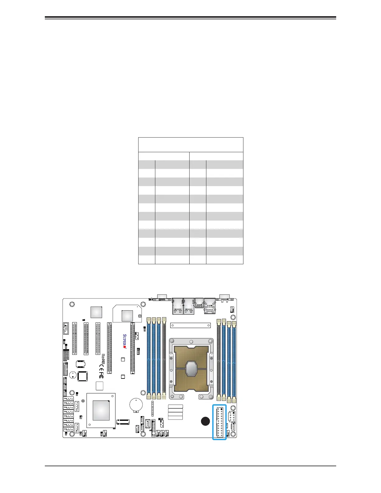
2.7 Connectors
Power Connections
ATX Power Supply Connector
The 24-pin power supply connector (JPWR2) meets the ATX SSI EPS 12V specication.
You must also connect the 8-pin (JPWR1) processor power connector to the power supply.
Required Connection
1
ATX Power 24-pin Connector
Pin Denitions
Pin# Denition Pin# Denition
13 +3.3V 1 +3.3V
14 -12V 2 +3.3V
15 Ground 3 Ground
16 PS_ON 4 +5V
17 Ground 5 Ground
18 Ground 6 +5V
19 Ground 7 Ground
20 Res (NC) 8 PWR_OK
21 +5V 9 5VSB
22 +5V 10 +12V
23 +5V 11 +12V
24 Ground 12 +3.3V
1. 24-Pin ATX PWR

 Loading...


