47
Chapter 2: Installation
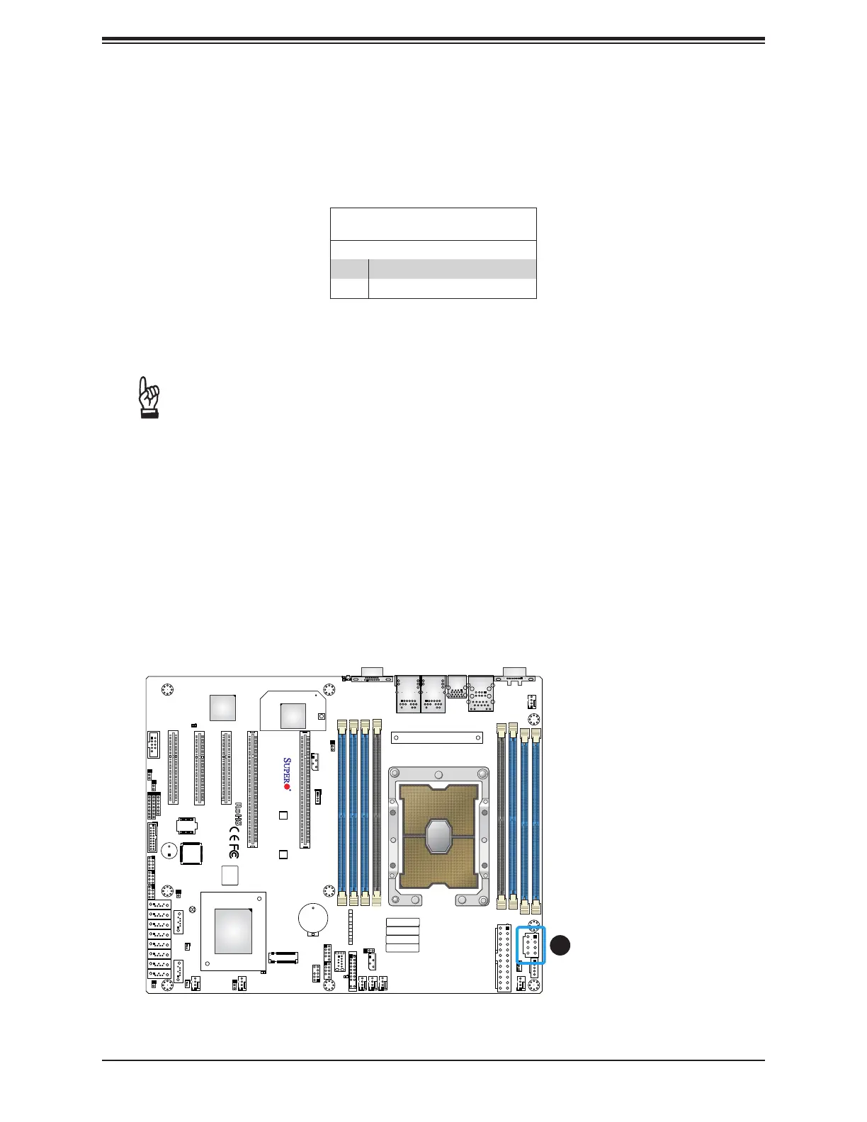
Required Connection
8-pin Power
Pin Denitions
Pin# Denition
1 - 4 Ground
5 - 8 P12V (12V Power)
8-Pin Power Connector
JPWR1 is an 8-pin 12V DC power input for the CPU that must be connected to the power
supply. Refer to the table below for pin denitions..
SAN MAC
DESIGNED IN USA
BIOS
LICENSE
X11SPi-TF
REV:1.02
IPMI CODE
MAC CODE
BAR CODE
JTPM1
JPWR1
MH11
MH10
JRK1
BT1
SP1
+
LEDBMC
LE3
LEDPWR
C
JL1
JOH1
JBT1
JSTBY1
JSD1
JSD2
JWD1
JPG1
JPME2
JIPMB1
JNVI2C1
FAN4
FAN3 FAN2
FAN1
FANA
FANB
FAN5
JPI2C1
JD1
I-SGPIO2
S-SGPIO1
I-SGPIO1
I-SATA4
I-SATA5
I-SATA6
I-SATA7
I-SATA0
S-SATA0
S-SATA1
I-SATA1
I-SATA2
I-SATA3
JF1
JPWR2
M.2 PCI-E 3.0 X4
USB10(3.0)
USB8/9(3.0)
USB6/7(3.0)
USB4/5
USB2/3
COM1
COM2
USB0/1
IPMI_LAN
LAN1
LAN2
VGA
UID-SW
UID-LED
PCH SLOT1 PCI-E 3.0 X4(IN X8)
CPU SLOT2 PCI-E 3.0 X8
CPU SLOT3 PCI-E 3.0 X8
CPU SLOT4 PCI-E 3.0 X16
CPU SLOT6 PCI-E 3.0 X16
CPU
DIMMF1
DIMME1
DIMMD1
DIMMD2
DIMMA2
DIMMA1
DIMMB1
RST
JF1
ON
PWR UID
LED
PS
FAIL 1
NIC
2
NIC
NMIX
PWRHDD
LEDLED
Intel
C622
ASpeed
AST2500
JPTG1
Intel
X557
DIMMC1
1
Important: To provide adequate power supply to the motherboard, be sure to connect
the 24-pin ATX PWR and the 8-pin PWR connectors to the power supply. Failure to
do so may void the manufacturer warranty on your power supply and motherboard.
1. 8-Pin PWR

 Loading...


