42
Super X11SPi-TF User's Manual
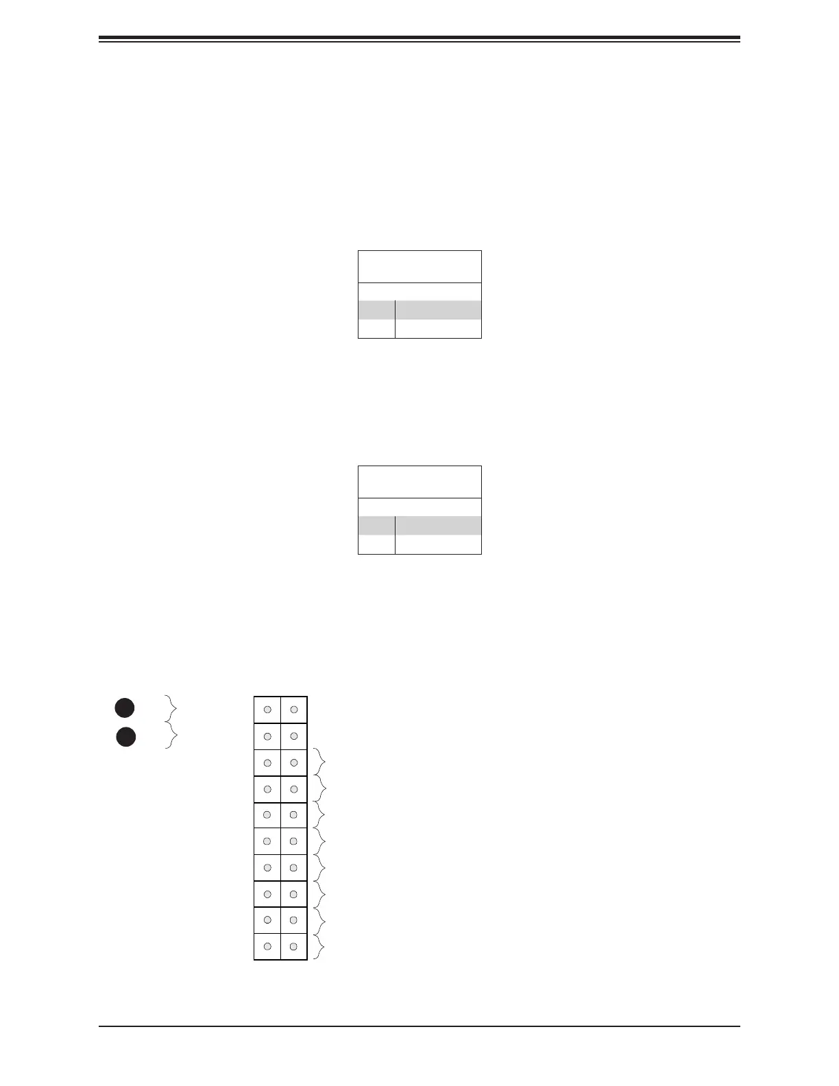
Power Button
UID LED
NIC1 Active LED
Reset Button
HDD LED
PWR LED
Reset
PWR
3.3V Stby
3.3V Stby
Ground
19
X
Ground
X
3.3V Stby
20
1 2
Ground
Power Fail LED
NIC2 Active LED
NMI
3.3V
OH/Fan Fail LED
3.3V Stby
1
2
1. PWR Button
2. Reset Button
Reset Button
Pin Denitions (JF1)
Pins Denition
3 Reset
4 Ground
Power Button
Pin Denitions (JF1)
Pins Denition
1 Signal
2 Ground
Power Button
The Power Button connection is located on pins 1 and 2 of JF1. Momentarily contacting both
pins will power on/o the system. This button can also be congured to function as a suspend
button (with a setting in the BIOS - see Chapter 4). To turn o the power when the system
is in suspend mode, press the button for 4 seconds or longer. Refer to the table below for
pin denitions.
Reset Button
The Reset Button connection is located on pins 3 and 4 of JF1. Attach it to a hardware reset
switch on the computer case to reset the system. Refer to the table below for pin denitions.

 Loading...


