44
Super X11SPi-TF User's Manual
Power Button
UID LED
NIC1 Active LED
Reset Button
HDD LED
PWR LED
Reset
PWR
3.3V Stby
3.3V Stby
Ground
19
X
Ground
X
3.3V Stby
20
1 2
Ground
Power Fail LED
NIC2 Active LED
NMI
3.3V
OH/Fan Fail LED
3.3V Stby
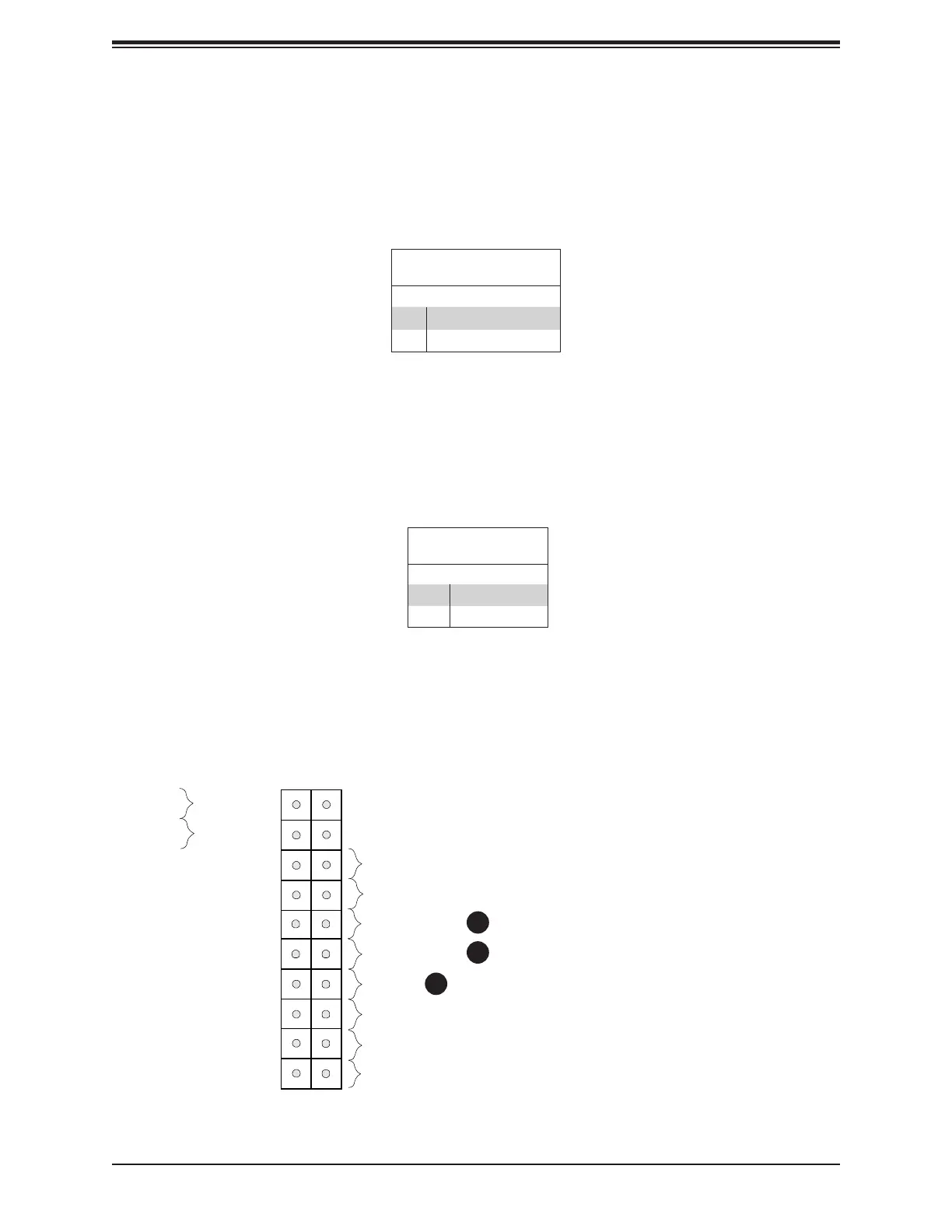
NIC1/NIC2 (LAN1/LAN2)
The NIC (Network Interface Controller) LED connection for LAN port 1 is located on pins
11 and 12 of JF1, and LAN port 2 is on pins 9 and 10. Attach the NIC LED cables here to
display network activity. Refer to the table below for pin denitions.
1. NIC2 LED
2. NIC1 LED
3. HDD LED
LAN1/LAN2 LED
Pin Denitions (JF1)
Pin# Denition
9 NIC 2 Activity LED
11 NIC 1 Activity LED
1
2
3
HDD LED
The HDD LED connection is located on pins 13 and 14 of JF1. Attach a cable to pin 14 to
show hard drive activity status. Refer to the table below for pin denitions.
HDD LED
Pin Denitions (JF1)
Pins Denition
13 3.3V Stdby
14 HDD Active

 Loading...


