54
Super X11SPi-TF User's Manual
SAN MAC
DESIGNED IN USA
BIOS
LICENSE
X11SPi-TF
REV:1.02
IPMI CODE
MAC CODE
BAR CODE
JTPM1
JPWR1
MH11
MH10
JRK1
BT1
SP1
+
LEDBMC
LE3
LEDPWR
C
JL1
JOH1
JBT1
JSTBY1
JSD1
JSD2
JWD1
JPG1
JPME2
JIPMB1
JNVI2C1
FAN4
FAN3 FAN2
FAN1
FANA
FANB
FAN5
JPI2C1
JD1
I-SGPIO2
S-SGPIO1
I-SGPIO1
I-SATA4
I-SATA5
I-SATA6
I-SATA7
I-SATA0
S-SATA0
S-SATA1
I-SATA1
I-SATA2
I-SATA3
JF1
JPWR2
M.2 PCI-E 3.0 X4
USB10(3.0)
USB8/9(3.0)
USB6/7(3.0)
USB4/5
USB2/3
COM1
COM2
USB0/1
IPMI_LAN
LAN1
LAN2
VGA
UID-SW
UID-LED
PCH SLOT1 PCI-E 3.0 X4(IN X8)
CPU SLOT2 PCI-E 3.0 X8
CPU SLOT3 PCI-E 3.0 X8
CPU SLOT4 PCI-E 3.0 X16
CPU SLOT6 PCI-E 3.0 X16
CPU
DIMMF1
DIMME1
DIMMD1
DIMMD2
DIMMA2
DIMMA1
DIMMB1
RST
JF1
ON
PWR UID
LED
PS
FAIL 1
NIC
2
NIC
NMIX
PWRHDD
LEDLED
Intel
C622
ASpeed
AST2500
JPTG1
Intel
X557
DIMMC1
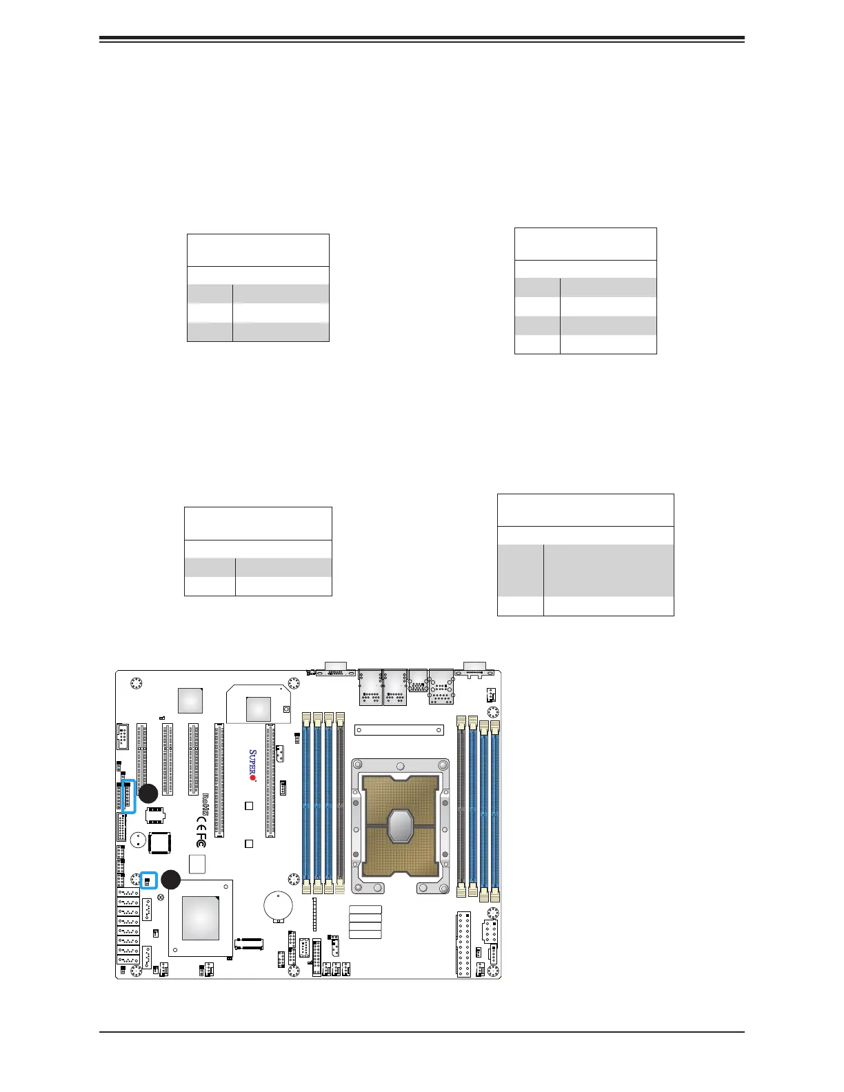
Power LED/Speaker
Pins 1-3 of JD1 are used for power LED indication, and pins 4-7 are for the speaker. Please
note that the speaker connector pins (4-7) are used with an external speaker. If you wish to
use the onboard speaker, you should close pins 6-7 with a cap. Refer to the tables below
for pin denitions.
PWR LED Connector
Pin Denitions
Pin# Signal
1 JD1_PIN1
2 FP_PWR_LED
3 FP_PWR_LED
Speaker Connector
Pin Denitions
Pin# Signal
4 P5V
5 Key
6 R_SPKPIN_N
7 R_SPKPIN
Overheat/Fan Fail LED Header
The JOH1 header is used to connect an LED indicator to provide warnings of chassis
overheating and fan failure. This LED will blink when a fan failure occurs. Refer to the tables
below for pin denitions.
Overheat LED Header
Status
State Denition
Solid Overheat
Blinking Fan Fail
Overheat LED
Pin Denitions
Pin# Signal
1
Pull high to +3.3V
power through 330-ohm
resistor
2 OH Active
1. Speaker Header
2. Overheat/Fan Fail LED
Header
1
2

 Loading...


