2-8
C7H61 User’s Manual
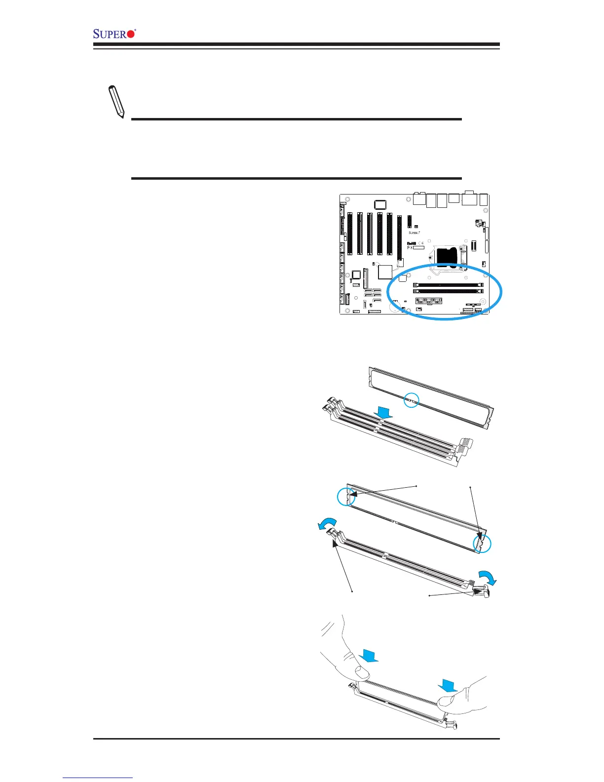
2-3 Installing DDR3 Memory
Note: Check the Supermicro website for recommended memory mod-
ules.
CAUTION
Exercise extreme care when installing or removing DIMM
modules to prevent any possible damage.
DIMM Installation
1. Insert the desired number of DIMMs
into the memory slots, starting with
DIMM1A (Slot A, Channel 1, see the
next page for the location). For best
performance, please use the memory
modules of the same type and speed
in the same bank.
2. Push the release tabs outwards on
both ends of the DIMM slot to unlock
it.
Release Tabs
Notches
3. Align the key of the DIMM mod-
ule with the receptive point on the
memory slot.
Press both notches
straight down into
the memory slot.
4. Align the notches on both ends of
the module against the receptive
points on the ends of the slot.
5. Use two thumbs together to press
the notches on both ends of the
module straight down into the slot
until the module snaps into place.
6. Press the release tabs to the lock
positions to secure the DIMM module
into the slot.
Removing Memory Modules
Reverse the steps above to remove the
DIMM modules from the motherboard.
JPW2
JPW1
JWOL1
1
3
10
9
1
DIMM1
DIMM3
JF1
1
2
15
Tested to Comply
With FCC Standards
FOR HOME OR OFFICE USE
DESIGNED IN USA
2
J14
1
7
10
J13
1
2
JUSB30
19
11 10
MH10
1
JD1
+
SP1
JSD1
1
JTPM1
2
1
20
19
I-SATA0
1
I-SATA1
I-SATA2
I-SATA3
A-SATA0
A-SATA1
JITP1
60
2
59
1
B1
+
128
1
2
J34
COM2
1
5
6
9
COM5
1
5
COM6
1
5
6
9
COM7
1
5
6
9
COM8
1
5
6
9
1
5
6
COM3
9
1
5
6
COM4
9
BIOS LICENSE
1
JWOR1
JP2
JP1
JSPDIF_OUT
JSPDIF_IN
JI2C3JL1 JI2C4 JBT1
JP3
1
JPME2
JI2C1
1
1
JI2C2
JUSBLAN1
JUSBLAN2
A
LED1
C
LED2
C
A
R474
JPUSB1
1
JWD1
1
JPAC1
JLED1
1
1
JCPUVRD_SMB
FAN4
FAN1
1
FAN3
4
4 1
FAN2
MH6
MH7
JAUDIO1
103
128
64
39
38
2-3:Disable(Default)
1-2:Enable
JPUSB1:USB WAKE UP
2-3:Disable
1-2:RST(Default)
JWD1:Watch Dog
OFF:NORMAL
ON:ME MANUFACTURING MODE
JPME2
VCC
GND
SW
RST
SW
PWR
GND
PWR
LED-
LED-
HDD
LED+
HDD
LED+
PWR
PRINTER
SLOT6 PCI-E 2.0/3.0 X16
SLOT5 PCI 33MHz
SLOT4 PCI 33MHz
SLOT3 PCI 33MHz
OFF:DISABLE
ON:ENABLE
JI2C3/JI2C4:I2C BUS FOR PCI SLOT
AUDIO AC97 AND HD AUDIO JUMPER
USB10/11
USB8/9
USB3.0-0/1
JLED1:
JL1:
3PIN POWER LED
CHASSIS
AUDIO FP
SLOT1 PCI 33MHz
BUZZER
SLOT2 PCI 33MHz
JBT1
JTPM1:TPM/PORT80
CMOS CLEAR
ON:CLEAR
OFF:NORMAL
JWOR:WAKE ON RING
JD1:
SPEAKER:1-4
BUZZER:3-4
JPAC1:ONBOARD AUDIO ENABLE/DISABLE
1-2:ENABLE
2-3:DISABLE
ON:AC'97
JHD_AC1:
OFF:HD AUDIO
SATA DOM PWR
SLOT7 PCI-E 2.0 X1
UNB NON-ECC DDR3 DIMM REQUIRED
HD AUDIO
JWOL:WAKE ON LAN
DIMMA1 DIMMB1
JI2C1/JI2C2:I2C BUS FOR PCI-E SLOT
OFF:DISABLE
ON:ENABLE
RST
ON
PWR
LAN2/
USB4/5
LED
OH/FF
X
LED
HDD
NIC1
NIC2
LED
PWR
USB2/3
LAN1/
HDMI/DP
VGA/COM1
/CPU FAN
INTRUSION
KB/MOUSE & USB0/1