2-22
C7H61 User’s Manual
JPW2
JPW1
JWOL1
1
3
10
9
1
DIMM1
DIMM3
JF1
1
2
15
Tested to Comply
With FCC Standards
FOR HOME OR OFFICE USE
DESIGNED IN USA
2
J14
1
7
10
J13
1
2
JUSB30
19
11 10
MH10
1
JD1
+
SP1
JSD1
1
JTPM1
2
1
20
19
I-SATA0
1
I-SATA1
I-SATA2
I-SATA3
A-SATA0
A-SATA1
JITP1
60
2
59
1
B1
+
128
1
2
J34
COM2
1
5
6
9
COM5
1
5
COM6
1
5
6
9
COM7
1
5
6
9
COM8
1
5
6
9
1
5
6
COM3
9
1
5
6
COM4
9
BIOS LICENSE
1
JWOR1
JP2
JP1
JSPDIF_OUT
JSPDIF_IN
JI2C3JL1 JI2C4 JBT1
JP3
1
JPME2
JI2C1
1
1
JI2C2
JUSBLAN1
JUSBLAN2
A
LED1
C
LED2
C
A
R474
JPUSB1
1
JWD1
1
JPAC1
JLED1
1
1
JCPUVRD_SMB
FAN4
FAN1
1
FAN3
4
4 1
FAN2
MH6
MH7
JAUDIO1
103
128
64
39
38
2-3:Disable(Default)
1-2:Enable
JPUSB1:USB WAKE UP
2-3:Disable
1-2:RST(Default)
JWD1:Watch Dog
OFF:NORMAL
ON:ME MANUFACTURING MODE
JPME2
VCC
GND
SW
RST
SW
PWR
GND
PWR
LED-
LED-
HDD
LED+
HDD
LED+
PWR
PRINTER
SLOT6 PCI-E 2.0/3.0 X16
SLOT5 PCI 33MHz
SLOT4 PCI 33MHz
SLOT3 PCI 33MHz
OFF:DISABLE
ON:ENABLE
JI2C3/JI2C4:I2C BUS FOR PCI SLOT
AUDIO AC97 AND HD AUDIO JUMPER
USB10/11
USB8/9
USB3.0-0/1
JLED1:
JL1:
3PIN POWER LED
CHASSIS
AUDIO FP
SLOT1 PCI 33MHz
BUZZER
SLOT2 PCI 33MHz
JBT1
JTPM1:TPM/PORT80
CMOS CLEAR
ON:CLEAR
OFF:NORMAL
JWOR:WAKE ON RING
JD1:
SPEAKER:1-4
BUZZER:3-4
JPAC1:ONBOARD AUDIO ENABLE/DISABLE
1-2:ENABLE
2-3:DISABLE
ON:AC'97
JHD_AC1:
OFF:HD AUDIO
SATA DOM PWR
SLOT7 PCI-E 2.0 X1
UNB NON-ECC DDR3 DIMM REQUIRED
HD AUDIO
JWOL:WAKE ON LAN
DIMMA1 DIMMB1
JI2C1/JI2C2:I2C BUS FOR PCI-E SLOT
OFF:DISABLE
ON:ENABLE
RST
ON
PWR
LAN2/
USB4/5
LED
OH/FF
X
LED
HDD
NIC1
NIC2
LED
PWR
USB2/3
LAN1/
HDMI/DP
VGA/COM1
/CPU FAN
INTRUSION
KB/MOUSE & USB0/1
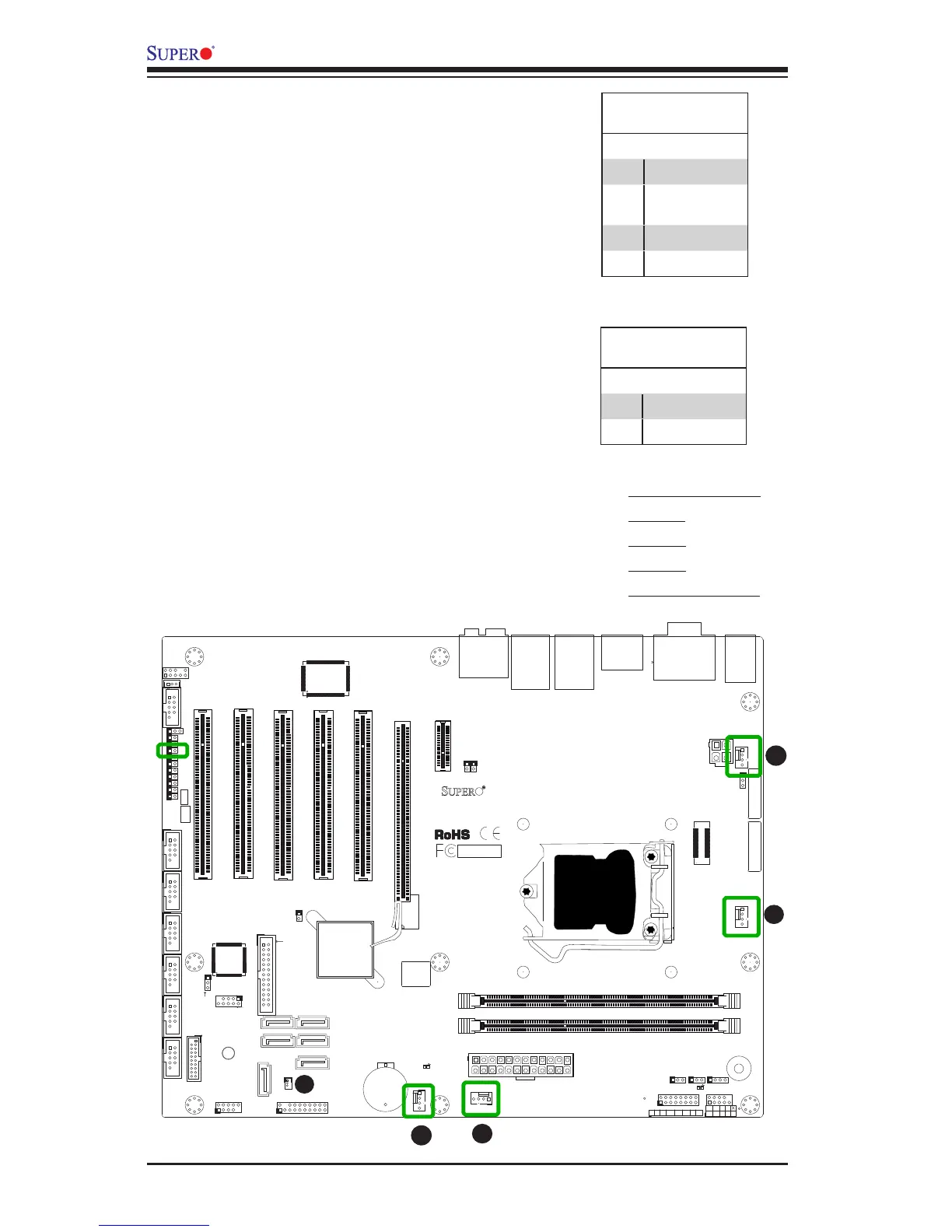
Fan Header
Pin Denitions
Pin# Denition
1 Ground (Black)
2 2.5A/+12V
(Red)
3 Tachometer
4 PWM_Control
Fan Headers (Fan 1 ~ Fan 4)
The C7H61 has four fan headers (Fan 1~Fan 4).
These fans are 4-pin fan headers. Although pins
1-3 of the fan headers are backward compatible
with the traditional 3-pin fans, we recommend
the use 4-pin fans to take advantage of the fan
speed control in the BIOS Hardware Monitoring
section. This allows the BIOS to automatically
adjust fan speeds based on the motherboard's
detected system temperature. Refer to the table
on the right for pin denitions.
A
B
A. Fan 1 (CPU Fan)
B. Fan 2
C. Fan 3
D. Fan 4
E. Chassis Intrusion
C
D
E
Chassis Intrusion (JL1)
A Chassis Intrusion header is located at JL1 on
the motherboard. Attach the appropriate cable
from the chassis to inform you of a chassis intru-
sion when the chassis is opened.
Chassis Intrusion
Pin Denitions (JL1)
Pin# Denition
1 Intrusion Input
2 Ground