Chapter 2: Installation
2-21
JPW2
JPW1
JWOL1
1
3
10
9
1
DIMM1
DIMM3
JF1
1
2
15
Tested to Comply
With FCC Standards
FOR HOME OR OFFICE USE
DESIGNED IN USA
2
J14
1
7
10
J13
1
2
JUSB30
19
11 10
MH10
1
JD1
+
SP1
JSD1
1
JTPM1
2
1
20
19
I-SATA0
1
I-SATA1
I-SATA2
I-SATA3
A-SATA0
A-SATA1
JITP1
60
2
59
1
B1
+
128
1
2
J34
COM2
1
5
6
9
COM5
1
5
COM6
1
5
6
9
COM7
1
5
6
9
COM8
1
5
6
9
1
5
6
COM3
9
1
5
6
COM4
9
BIOS LICENSE
1
JWOR1
JP2
JP1
JSPDIF_OUT
JSPDIF_IN
JI2C3JL1 JI2C4 JBT1
JP3
1
JPME2
JI2C1
1
1
JI2C2
JUSBLAN1
JUSBLAN2
A
LED1
C
LED2
C
A
R474
JPUSB1
1
JWD1
1
JPAC1
JLED1
1
1
JCPUVRD_SMB
FAN4
FAN1
1
FAN3
4
4 1
FAN2
MH6
MH7
JAUDIO1
103
128
64
39
38
2-3:Disable(Default)
1-2:Enable
JPUSB1:USB WAKE UP
2-3:Disable
1-2:RST(Default)
JWD1:Watch Dog
OFF:NORMAL
ON:ME MANUFACTURING MODE
JPME2
VCC
GND
SW
RST
SW
PWR
GND
PWR
LED-
LED-
HDD
LED+
HDD
LED+
PWR
PRINTER
SLOT6 PCI-E 2.0/3.0 X16
SLOT5 PCI 33MHz
SLOT4 PCI 33MHz
SLOT3 PCI 33MHz
OFF:DISABLE
ON:ENABLE
JI2C3/JI2C4:I2C BUS FOR PCI SLOT
AUDIO AC97 AND HD AUDIO JUMPER
USB10/11
USB8/9
USB3.0-0/1
JLED1:
JL1:
3PIN POWER LED
CHASSIS
AUDIO FP
SLOT1 PCI 33MHz
BUZZER
SLOT2 PCI 33MHz
JBT1
JTPM1:TPM/PORT80
CMOS CLEAR
ON:CLEAR
OFF:NORMAL
JWOR:WAKE ON RING
JD1:
SPEAKER:1-4
BUZZER:3-4
JPAC1:ONBOARD AUDIO ENABLE/DISABLE
1-2:ENABLE
2-3:DISABLE
ON:AC'97
JHD_AC1:
OFF:HD AUDIO
SATA DOM PWR
SLOT7 PCI-E 2.0 X1
UNB NON-ECC DDR3 DIMM REQUIRED
HD AUDIO
JWOL:WAKE ON LAN
DIMMA1 DIMMB1
JI2C1/JI2C2:I2C BUS FOR PCI-E SLOT
OFF:DISABLE
ON:ENABLE
RST
ON
PWR
LAN2/
USB4/5
LED
OH/FF
X
LED
HDD
NIC1
NIC2
LED
PWR
USB2/3
LAN1/
HDMI/DP
VGA/COM1
/CPU FAN
INTRUSION
KB/MOUSE & USB0/1
2-6 Connecting Cables
This section provides brief descriptions and pin-out denitions for onboard headers
and connectors. Be sure to use the correct cable for each header or connector. For
information on Backpanel USB and Front Panel USB ports, refer to Page 2-14. For
Front Panel pin dentions, please refer to Page 2-17.
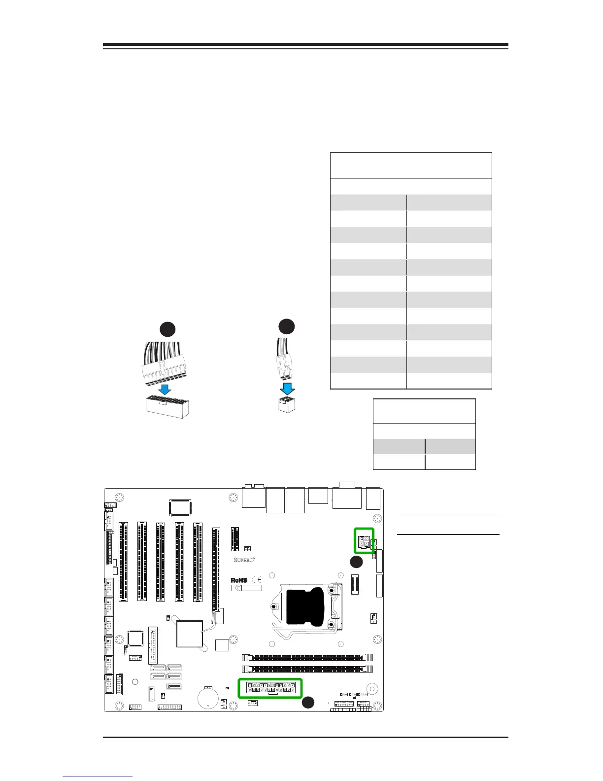
A. 24-Pin ATX Main PWR
B. 4-Pin Processor PWR
ATX Power 24-pin Connector
Pin Denitions (JPW1)
Pin# Denition Pin # Denition
13 +3.3V 1 +3.3V
14 -12V 2 +3.3V
15 COM 3 COM
16 PS_ON 4 +5V
17 COM 5 COM
18 COM 6 +5V
19 COM 7 COM
20 Res (NC) 8 PWR_OK
21 +5V 9 5VSB
22 +5V 10 +12V
23 +5V 11 +12V
24 COM 12 +3.3V
(Required)
12V 4-pin Power Connec-
tor Pin Denitions
Pins Denition
1 through 2 Ground
3 through 4 +12VDC
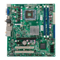
ATX Main PWR & CPU PWR
Connectors (JPW1 & JPW2)
The 24-pin main power connector
(JPW1) is used to provide power to the
motherboard. The 4-pin Aux PWR con-
nector (JPW2) may also be required for
the processor. These power connectors
meet the SSI EPS 12V specication. See
the table on the right for pin denitions.
4-Pin Processor PWR
A
B
24-Pin Main PWR
A
B