2-20
Supermicro C7Z270-PG Motherboard User’s Manual
Power Button
The Power Button connection is located
on pins 1 and 2 of JF1. Momentarily
contacting both pins will power on/off
the system. This button can also be con-
gured to function as a suspend button
(with a setting in the BIOS - see Chapter
4). To turn off the power in the suspend
mode, press the button for at least 4
seconds. Refer to the table on the right
for pin denitions.
Power Button
Pin Denitions (JF1)
Pin# Denition
1 Power Button
2 Ground
Reset Button
The Reset Button connection is located
on pins 3 and 4 of JF1. Attach it to a
hardware reset switch on the computer
case to reset the system. Refer to the
table on the right for pin denitions.
Reset Button
Pin Denitions (JF1)
Pin# Denition
3 Reset Button
4 Ground
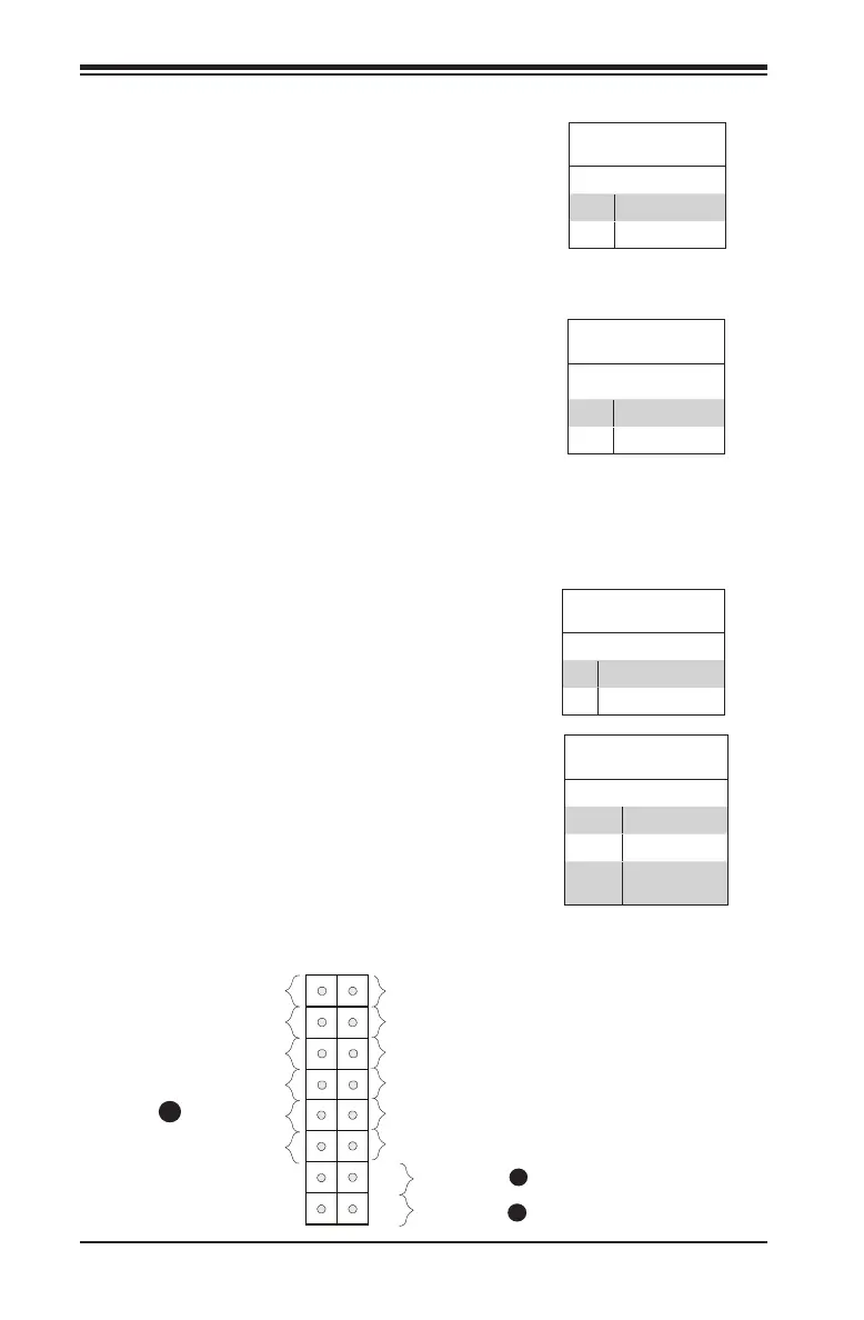
A. Reset Button
B. PWR Button
C. OH/Fan Fall LED
A
B
Power Button
LED
NIC1 LED
Reset Button
HDD LED
Power LED
Reset
PWR
Vcc
Ground
Ground
X
X
Vcc
Vcc
Vcc
NIC2 LED
Vcc
Overheat (OH)/Fan Fail
Connect an LED cable to OH/Fan Fail
connections on pins 7 and 8 of JF1 to
provide warnings for chassis overheat/
fan failure. Refer to the table on the right
for pin denitions.
OH/Fan Fail LED
Pin Denitions (JF1)
Pin# Denition
7 Vcc
8 OH/Fan Fail LED
OH/Fan Fail Indicator
Status
State Denition
Off Normal
On Overheat
Flash-
ing
Fan Fail
C