Chapter 2: Installation
2-27
PRESS FIT
J*
MH15
MH14
MH13
MH12
MH11
MH10
S12
JTBT
B1
JBT1
U6
JSTBY1
SP1
JD1
JF1
JSD1
FAN5
FAN1
FAN4
FAN2
FAN3
S8
JTPM1
JPW1
LED3
A
C
LED2
LED1
JPW2
JL2
JSPDIF_OUT
JI2C2
JI2C1
JL1
LED4
JPAC1
JPL2
JBR1
JVR1
JLED1
JPL1
JWD1
JPME2
DESIGNED IN USA
C7Z270-PG
REV:1.00
BIOS LICENSE
MAC CODE
BAR CODE
2
2-3:DISABLE
1-2:ENABLE
JPL2:LAN2
LAN2
LAN1
ON
PWR
RST
XOH/FF
NIC
NIC
1LED
HDD
LED
PWR
OFF:DISABLE
ON :ENABLE
JI2C1/JI2C2
AUDIO FP
3 PIN POWER LED
JLED1:
ON:BIOS RECOVERY
COM1
JTPM1:
TPM/PORT80
OFF:NORMAL
JBR1
JL1:
CHASSIS
INTRUSION
USB6/7
USB4/5
USB2/3
USB 14/15 (3.0)
PCIE M.2 CONNECTOR 1
CPU SLOT1 PCI-E 3.0 X8 (IN X16)
1-2:RST
2-3:NMI
WATCH DOG
JWD1:
CPU SLOT3 PCI-E 3.0 X16
U.2 CONNECTOR 1
U.2 CONNECTOR 2
I-SATA4
I-SATA5
BUZZER:3-4
JD1:
SPEAKER:1-4
PCH SLOT4 PCI-E 3.0 X4
I-SATA2
I-SATA3
2-3:ME MANUFACTURING MODE
1-2:NORMAL
JPME2:
CPU SLOT5 PCI-E 3.0 X8 (IN X 16)
1-2:ENABLE
2-3:DISABLE
JPAC1:AUDIO
I-SATA0
I-SATA1
CPU SLOT7 PCI-E 3.0 X16
SYS_FAN2
PCIE M.2 CONNECTOR 2
SYS_FAN3
HD AUDIO
USB 12/13 (3.1)
USB 10/11(3.1)
2-3:DISABLE
JPL1:LAN1
1-2:ENABLE
USB8/9(3.0)
POWER BUTTON
DIMMB1
DIMMB2
DIMMA1
DIMMA2
HDMI/DP
RESET BUTTON
KB/MOUSE USB 0/1
SYS_FAN1
CPU_FAN1
CLEAR CMOS
CPU_FAN2
CPU
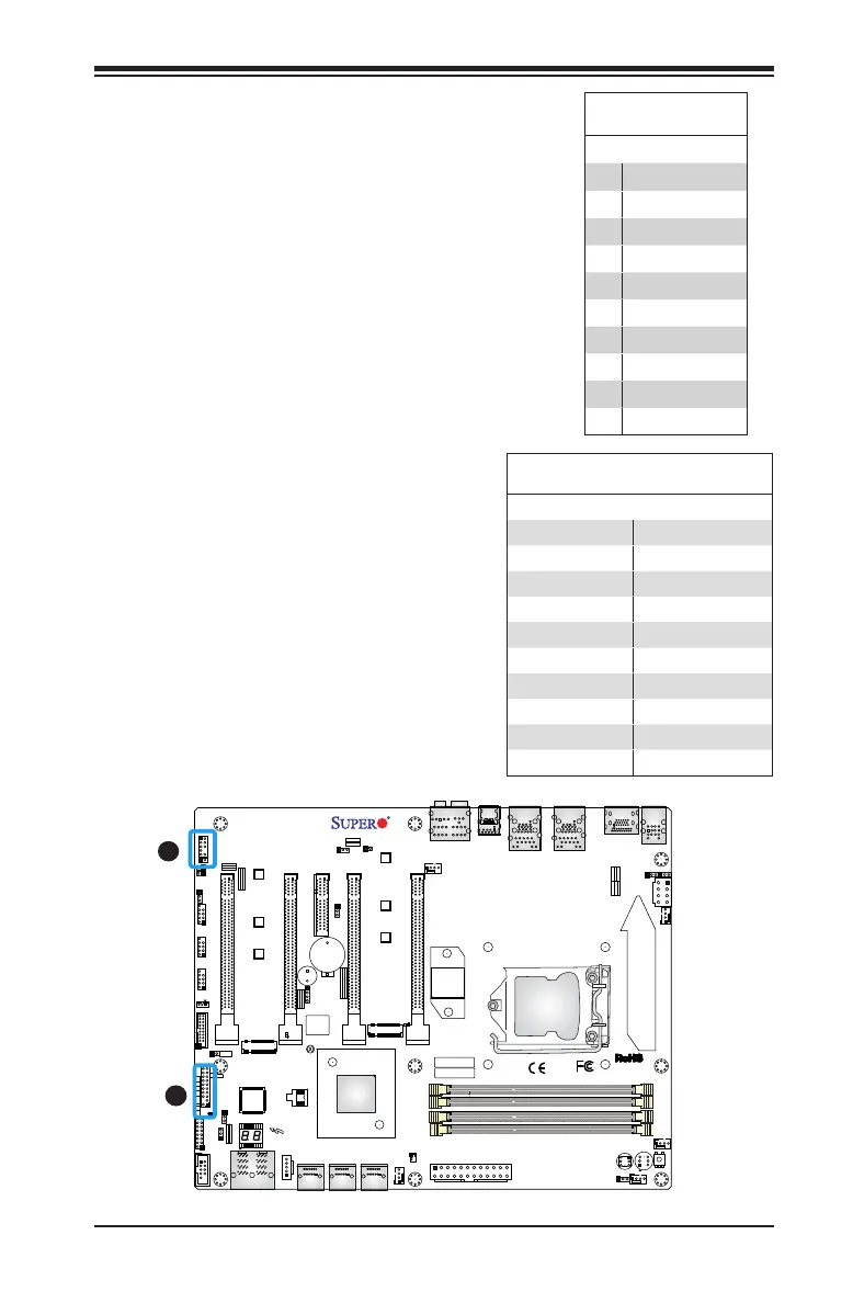
A. AUDIO FP
B.TPM Header
A
Front Panel Audio Header (AUDIO
FP)
A 10-pin Audio header is supported on
the motherboard. This header allows you
to connect the motherboard to a front
panel audio control panet, if needed.
Connect an audio cable to the audio
header to use this feature (not supplied).
See the table at right for pin denitions
for the header.
10-in Audio
Pin Denitions
Pin# Signal
1 Microphone_Left
2 Audio_Ground
3 Microphone_Right
4 Audio_Detect
5 Line_2_Right
6 Ground
7 Jack_Detect
8 Key
9 Line_2_Left
10 Ground
B
TPM Header/Port 80
A Trusted Platform Module/Port 80 head-
er is located at JTPM1 to provide TPM
support and Port 80 connection. Use this
header to enhance system performance
and data security. See the table on the
right for pin denitions.
TPM/Port 80 Header
Pin Denitions
Pin # Denition Pin # Denition
1 LCLK 2 GND
3 LFRAME# 4 <(KEY)>
5 LRESET# 6 +5V (X)
7 LAD 3 8 LAD 2
9 +3.3V 10 LAD1
11 LAD0 12 GND
13 SMB_CLK4 14 SMB_DAT4
15 +3V_DUAL 16 SERIRQ
17 GND 18 CLKRUN# (X)
19 LPCPD# 20 LDRQ# (X)