1-8
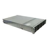
SUPERSERVER 6027TR-HTRF+/H70RF+/H71RF+ User's Manual
1-6 2U Twin
2
: System Notes
As a 2U Twin
2
confi guration, the SuperServer 6027TR-HTRF+/H70RF+/H71RF+ is
a unique server system. With four system boards incorporated into a single chassis
acting as four separate nodes, there are several points you should keep in mind.
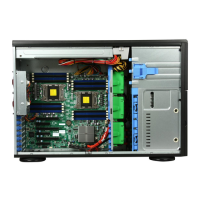
Nodes
Each of the four serverboards act as a separate node in the system. As independant
nodes, each may be powered off and on without affecting the others. In addition,
each node is a hot-swappable unit that may be removed from the rear of the chassis.
The nodes are connected to the server backplane by means of an adapter card.
Note: A guide pin is located between the upper and lower nodes on the inner chassis
wall. This guide pin also acts as a “stop” when a node is fully installed. If too much
force is used when inserting a node this pin may break off. Take care to slowly slide
a node in until you hear the “click” of the locking tab seating itself.
System Power
Dual 1620 Watt power supplies are used to provide the power for all four
serverboards. Each serverboard however, can be shut down independently of the
other with the power button on its own control panel.
SAS/SATA Backplane/Drives
As a system, the SuperServer 6027TR-HTRF+/H70RF+/H71RF+ supports the use
of twelve SAS/SATA drives. A single SAS/SATA backplane works to apply system-
based control for power and fan speed functions, yet at the same time logically
connects a set of three SAS/SATA drives to each serverboard. Consequently, RAID
setup is limited to a three-drive scheme (RAID cannot be spread across all twelve
drives). See the Drive Bay Installation/Removal section in Chapter 6 for the logical
hard drive and node confi guration.