6-16
SUPERSERVER 6027TR-HTRF+/H70RF+/H71RF+ User's Manual
6-10 Drive Bay Installation/Removal
Accessing the Drive Bays
SAS/SATA Drives: You do not need to access the inside of the chassis or remove
power to replace or swap SAS/SATA drives. Proceed to the next step for instructions.
You must use standard 1" high, SAS/SATA drives in the system.
Note: Refer to Supermicro's web site for setup guidelines: <http://www.supermicro.
com/support/manuals/>.
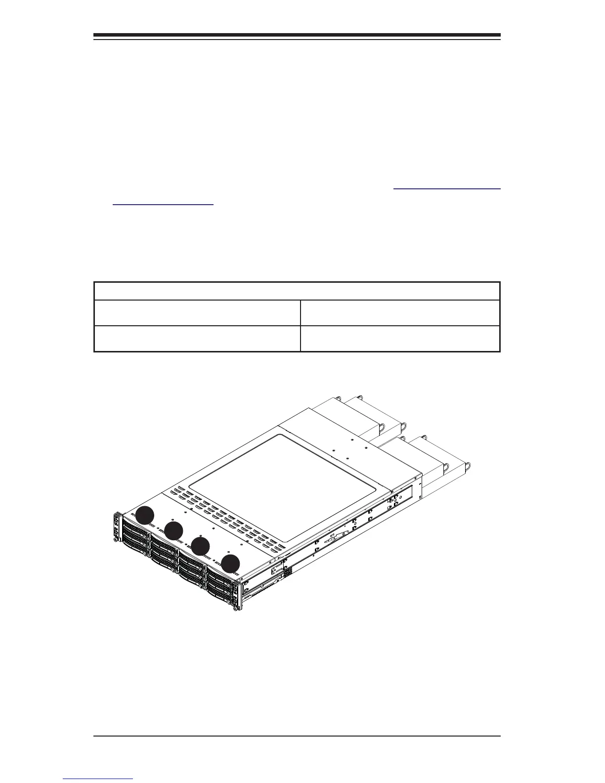
The SC827 chassis contains four individual motherboards in separate node drawers
(Figure 6-14). Each motherboard node controls a set of three hard drives. Note that
if a motherboard node drawer is pulled out of the chassis, the hard drives associated
with that node will power down as well.
Motherboard Drawer Locations in the Chassis
Motherboard B
Controls HDDs B1, B2 and B3
Motherboard D
Controls HDDs D1, D2 and D3
Motherboard A
Controls HDDs A1, A2 and A3
Motherboard C
Controls HDDs C1, C2 and C3
Figure 6-14. Hard Drives and the Corresponding Motherboards
MB: A
MB: B
MB: C
MB: D
1
A
1
B
1
C
1
D