5-16
SUPERSERVER 6027TR-HTRF+/H70RF+/H71RF+ User's Manual
5-8 Connector Defi nitions
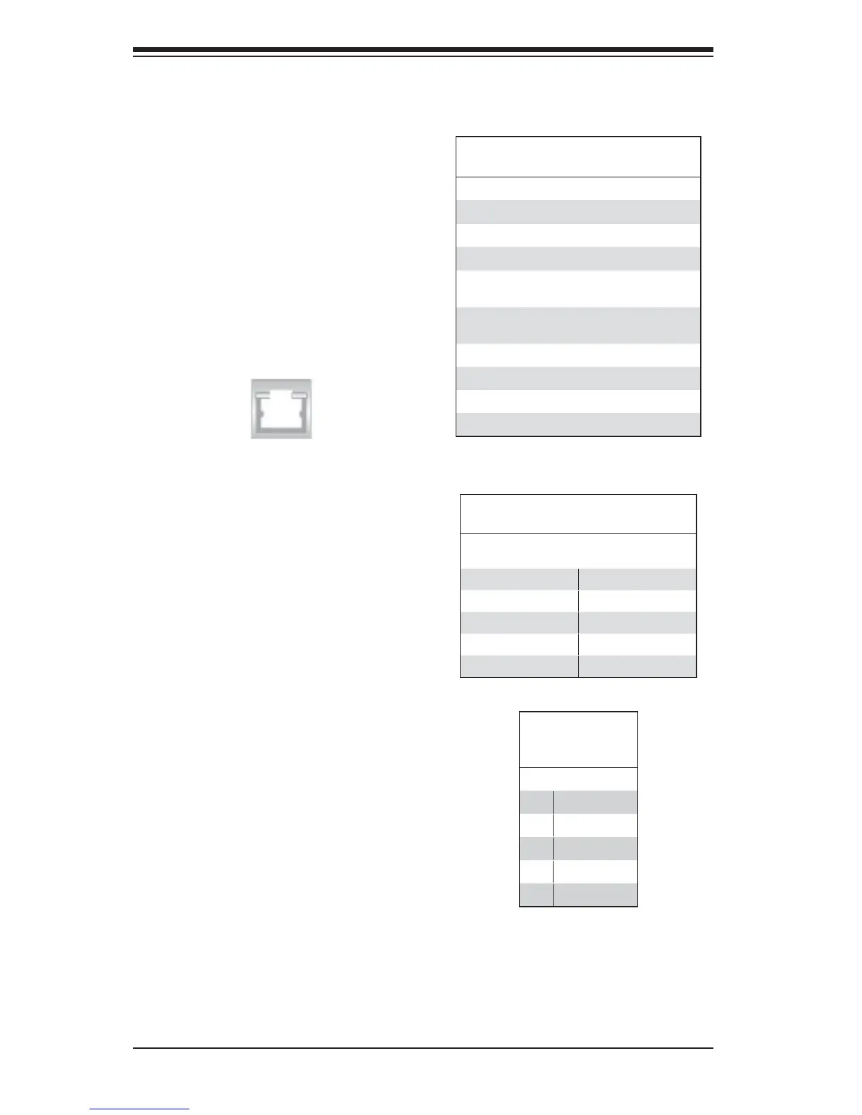
Ethernet LAN Ports
Two Gigabit Ethernet ports (LAN1/2)
are located on the I/O backplane on
the motherboard. In addition, an IPMI
Dedicated LAN is located above USB
0/1 ports on the backplane to provide
KVM support for IPMI 2.0. All these ports
accept RJ45 type cables.
Note: Please refer to the LED Indicator
Section for LAN LED information.
LAN Ports (LAN1/2)
Pin Defi nition
Pin# Defi nition Pin# Defi nition
1 P2V5SB 10 SGND
2 TD0+ 11 Act LED
3 TD0- 12 P3V3SB
4 TD1+ 13 Link 100 LED
(Yellow, +3V3SB)
5 TD1- 14 Link 1000 LED
(Yellow, +3V3SB)
6 TD2+ 15 Ground
7 TD2- 16 Ground
8 TD3+ 17 Ground
9 TD3- 18 Ground
NC indicates no connection.
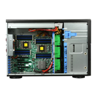
Universal Serial Bus (USB)
Two Universal Serial Bus ports (USB
0/1) are located on the I/O back panel. In
addition, a USB header, located next to
I-SATA 5, provides two front-accessible
USB connections (USB 2/3). (Cables are
not included.) See the tables on the right
for pin defi nitions.
USB (2/3)
Pin Defi nitions
USB 2
Pin# Defi nition
USB 3
Pin# Defi nition
1 +5V 1 +5V
2 PO- 2 PO-
3 PO+ 3 PO+
4 Ground 4 Ground
5 NC 5 Key
NC indicates no connection.
Backplane USB
(USB 0/1)
Pin Defi nitions
Pin# Defi nition
1 +5V
2 PO-
3 PO+
4 Ground
5NA