Do you have a question about the Supero SUPERSERVER 7047R-TRF and is the answer not in the manual?
Provides an overview of the SuperServer 7047R-TRF, its chassis, and included components.
Details the main features of the X9DRi-F serverboard, including processors, memory, and controllers.
Outlines the main features of the SC745TQ-R920B server chassis, including power, control panel, I/O, and cooling.
Explains Intel Intelligent Power Node Manager and Manageability Engine for power efficiency.
Provides contact information for Supermicro headquarters, Europe, and Asia-Pacific regions.
Provides a quick setup checklist for getting the SuperServer 7047R-TRF operational.
Details steps for inspecting the system box, choosing a location, and environmental considerations.
Covers preparation steps, including checking for rail assemblies and mounting screws for rack installation.
Provides critical rack and server precautions to ensure safe installation and operation.
Guides on installing the server into a rack unit using the optional rackmount kit.
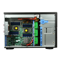
Instructs on opening the unit to verify serverboard installation and cable connections.
Guides on checking peripheral and hard drive installation, connections, and airflow.
Introduces the system interface, including LEDs and buttons on the control panel.
Explains the functions of the power and reset buttons located on the front chassis.
Details the meaning of the six LEDs on the front control panel for system status.
Describes the green and red LEDs on the hard drive carriers indicating activity and failure.
Introduces industry-standard warnings for potential bodily injury and advises consulting support.
Provides instructions on connecting the system to the power source and following installation guidelines.
Specifies building protection requirements for short-circuit and overcurrent, with voltage and amperage limits.
Warns to disconnect all power sources before accessing chassis interior for component installation or removal.
States that only trained and qualified personnel should install, replace, or service the equipment.
Notes that the unit is intended for restricted access areas, requiring special tools for entry.
Warns of explosion danger from incorrect battery replacement and disposal guidelines.
Advises disconnecting all connections to de-energize units with multiple power supply connections.
Warns of hazardous voltage or energy present on the backplane during operation and advises caution.
Emphasizes that equipment installation must comply with all local and national electrical codes.
States that product disposal must follow all national laws and regulations.
Warns that fans may still be turning when removed and to keep objects away from openings.
Advises using provided or designated cables/adapters to prevent malfunction or fire.
Provides precautions for handling the serverboard to prevent static discharge and physical damage.
Details the procedure for installing LGA2011 processors and heatsinks, including socket handling.
Guides on connecting data, power, and control panel cables to the serverboard.
Describes the rear panel I/O ports and their color coding according to PC 99 specification.
Explains how to install DDR3 DIMM modules into the serverboard's memory slots.
Details how to install PCI Express expansion cards using the riser card.
Provides a layout of the X9DRi-F serverboard, including jumper and connector locations.
Defines the pin assignments for various power connectors and front panel headers.
Explains how to modify motherboard operation using jumpers and details specific jumper settings.
Describes the onboard LEDs for LAN, IPMI, power, and BMC status.
Details the SATA ports on the motherboard and their pin definitions.
Guides on downloading and installing system drivers and utilities, including SuperDoctor III.
Explains how to install the onboard battery and warnings about incorrect installation.
Provides precautions for handling static-sensitive components to prevent damage.
Details connecting the front control panel to the serverboard for system status and alarm indications.
Explains the system fans, fan failure procedures, and air shroud removal/reinstallation.
Guides on installing SATA drives into the chassis drive bays and adding optional DVD-ROM drives.
Details the dual 920 Watt power supply modules and the procedure for replacing a failed unit.
Introduces the AMI BIOS Setup Utility and how to navigate its screens.
Describes the Main BIOS menu, system overview, and how to edit system time and date.
Covers various advanced BIOS settings related to boot features, CPU configuration, and power management.
Explains how to configure SmBIOS and System Event Log settings, including enabling/disabling and erasing.
Details IPMI System Event Log configuration and BMC Network Configuration settings.
Covers boot option priorities, deleting boot options, and security settings like passwords.
Allows configuration of Administrator and User passwords for BIOS access and system login.
Explains options for saving changes, discarding changes, and restoring default settings in the BIOS.
Lists AMIBIOS error beep codes, their messages, and descriptions for troubleshooting.
Lists supported processor types and requirements for the SuperServer 7047R-TRF.
Details the serverboard's memory support, including number of slots and capacity.
Lists the available PCI Express expansion slots for add-on cards.
Details the rated output power and voltages of the power supply modules.
Lists the recommended operating temperature and humidity ranges.
Outlines electromagnetic emissions, immunity, safety compliance, and perchlorate material warnings.
| Form Factor | 4U Rackmount |
|---|---|
| Chipset | Intel C602 |
| Maximum Memory | Up to 512GB |
| Networking | Dual Gigabit Ethernet |
| Operating System Support | Windows Server, Linux |
| CPU Socket | LGA 2011 |
| Memory Type | DDR3 |
| Memory Slots | 16 |
| SATA | 6 x SATA 3.0 |
| SAS | 6Gb/s (with optional SAS controller) |
| Management | IPMI 2.0 |